00195941-03-UM SiplaceCA-EN.pdf - 第304页
4 Setting Up and Commissioning User Manual SIPLACE CA 4.5 Setting Up the Placement Machine Edition 08/2011 EN 304 4.5.12 Inst allation of th e Comput er Unit of the CA4 and CA3 4.5.12.1 Computer Unit - Electrical Connect…

User Manual SIPLACE CA 4 Setting Up and Commissioning
Edition 08/2011 EN 4.5 Setting Up the Placement Machine
303
4.5.11.5 Fitting the Side Plates
Fasten the ground cable to each side plate (item 6 in fig. 4.5 - 15, page 293), as shown in fig.
4.5 - 17
, page 297.
Fix the side plate to the machine frame with 6 fillister head screws.
Continue with section 4.5.14 "Fitting the Main Fault Indicator", page 311.
4 Setting Up and Commissioning User Manual SIPLACE CA
4.5 Setting Up the Placement Machine Edition 08/2011 EN
304
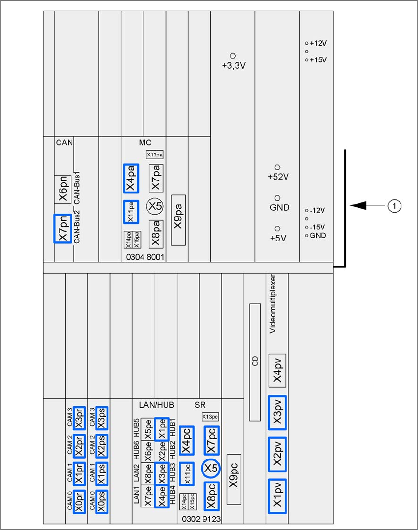
4.5.12 Installation of the Computer Unit of the CA4 and CA3
4.5.12.1 Computer Unit - Electrical Connection Points
4
Fig. 4.5 - 21 Computer unit, front panel - Connecting the plugs
(1) Cable guide plate
User Manual SIPLACE CA 4 Setting Up and Commissioning
Edition 08/2011 EN 4.5 Setting Up the Placement Machine
305
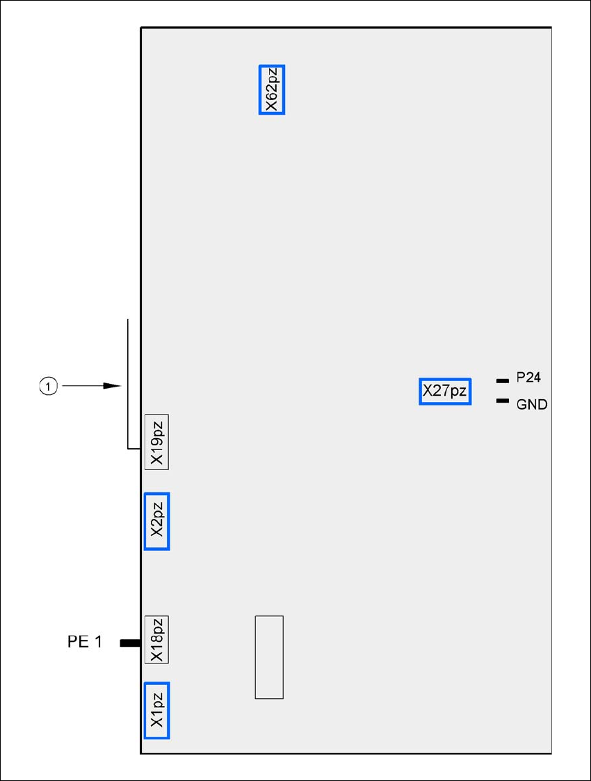
4
Fig. 4.5 - 22 Computer unit, back panel - Connecting the plugs
(1) Cable guide plate
Fan
Battery
+3.6V