00195941-03-UM SiplaceCA-EN.pdf - 第312页
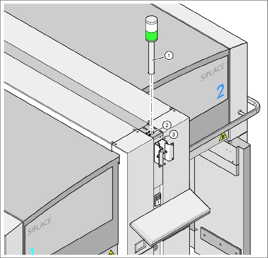
4 Setting Up and Commissioning User Manual SIPLACE CA 4.5 Setting Up the Placement Machine Edition 08/2011 EN 312 4 Fig. 4.5 - 24 Fitting the main indicator lamp (1) Main indicator lamp (2) Hole for the main indicator la…

User Manual SIPLACE CA 4 Setting Up and Commissioning
Edition 08/2011 EN 4.5 Setting Up the Placement Machine
311
4.5.13.3 Assemble Axis unit CA4, CA3 (Gantries 1 and 4)
Carefully lift the axis unit onto the rail in the extension kit.
Make sure that you do not squash any cables.
Push the axis unit into the extension kit as far as the stop.
Secure the axis unit with the fillister head screw.
Insert the cover.
Fasten the ground cable to the door (item 2 in fig. 4.5 - 15, page 293), as shown in fig. 4.5 -
17 on page 297.
Lock the doors.
4.5.13.4 Fitting the Side Plates
Fasten the ground cable to each side plate (item 6 in fig. 4.5 - 15, page 293), as shown in fig.
4.5 - 17
, page 297.
Fix the side plate to the machine frame with 6 fillister head screws.
4.5.14 Fitting the Main Fault Indicator
Connect the main fault indicator cables to the cables on the basic machine.
Insert the main fault indicator into the drilling (item 2 in fig. 4.5 - 24, page 312) until the tube
of the main fault indicator protrudes sufficiently into the clamp below.
Tighten the hexagon socket-head screw under the drilling (item 3 in fig. 4.5 - 24, page 312).
4 Setting Up and Commissioning User Manual SIPLACE CA
4.5 Setting Up the Placement Machine Edition 08/2011 EN
312
4
Fig. 4.5 - 24 Fitting the main indicator lamp
(1) Main indicator lamp
(2) Hole for the main indicator lamp
(3) Hole for the locking screw
4.5.15 Fixing the Monitor
Fix the monitor into place and connect the cables.
Check the cable connections
User Manual SIPLACE CA 4 Setting Up and Commissioning
Edition 08/2011 EN 4.5 Setting Up the Placement Machine
313
4.5.16 Integrating the Placement Machine into the Line
Observe the warnings in section 4.5.2, page 267.
For information about tools and equipment, refer to section 4.5.3, page 268.
4.5.16.1 Position Fork Lift Truck
4
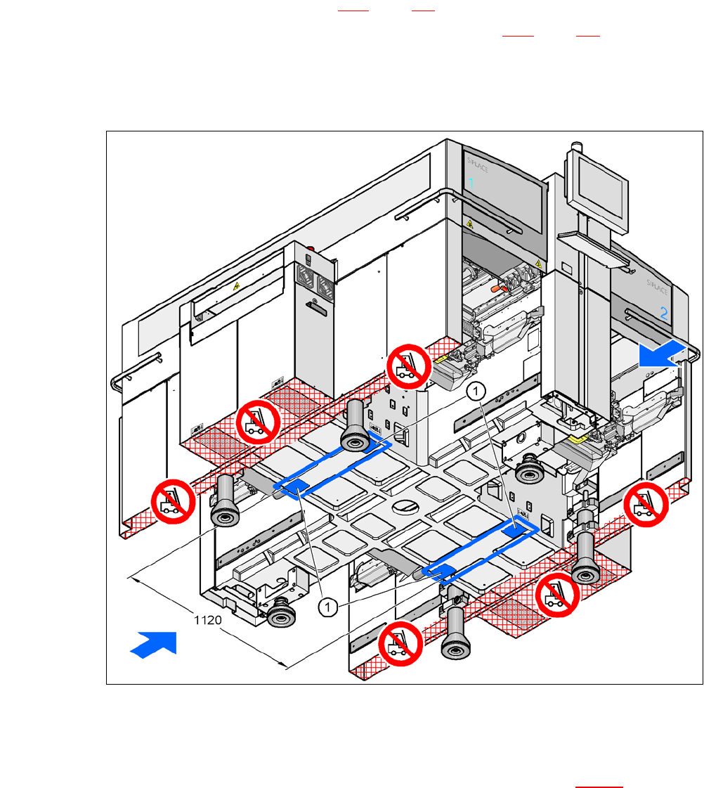
Fig. 4.5 - 25 Contact surfaces - Forks across the direction of PCB transport
(1) Contact surfaces for the forks of the fork-lift
Position the fork-lift truck at right angles to the PCB conveyor and open the forks until the con-
tact surfaces of the placement machine lie evenly on the forks (see fig. 4.5 - 25
).