00195941-03-UM SiplaceCA-EN.pdf - 第315页
User Manual SIPLACE CA 4 Setting Up and Commissioning Edition 08/2011 EN 4.5 Setting Up the Placement Machine 315 4.5.16.3 Aligning the Placement Machine to the Line Position the pl acement ma chine with the fork-lift …

4 Setting Up and Commissioning User Manual SIPLACE CA
4.5 Setting Up the Placement Machine Edition 08/2011 EN
314
WARNING 4
Before lifting the placement machine, observe the following points to avoid causing irreversible
damage to the machine:
– The distance between the forks must be between 800 and 900 mm. The attachment points
for the fork-lift truck can be seen in fig. 4.5 - 25
. The outer distance between the machine feet
is 1120 mm. Make sure you do not increase the distance between the forks so that the place-
ment machine is lifted under the sides of the machine frame, as this would distort the machine
frame.
When lifting the placement machine, make sure that the forks are loaded evenly. A firm sup-
port surface between the fork and the machine prevents the machine from tipping over when
lifted. This will also prevent a one-sided load on the machine feet, which would deform the
fixing of the machine feet. We recommend that a second person monitors the lifting of the ma-
chine and ensures that the placement machine does not tip over to one side when lifted by
the fork-lift truck.
4.5.16.2 Points that MUST be Noted when Transporting the Placement Machine
WARNING 4
When you are transporting the machine, make sure that all the feet are clear of the floor. If the
machine feet should drag along the floor during transportation or hit an obstacle, this could dam-
age the fixtures for the machine feet in the placement machine!
User Manual SIPLACE CA 4 Setting Up and Commissioning
Edition 08/2011 EN 4.5 Setting Up the Placement Machine
315
4.5.16.3 Aligning the Placement Machine to the Line
Position the placement machine with the fork-lift truck , so that it is in a free location in the line.
WARNING 4
Slowly lower the placement machine. A second person should look underneath to ensure that
all the machine foot touch the floor at the same time. If the machine feet on one side hit the
ground hard, the fixings may be damaged.
4
4.5.16.4 Aligning the Placement Machine with the Air Cushion Transport System
Place the four air cushions of the air cushion transport system beneath the machine frame.
Lift the placement machine and align it to the line.
Check the distance to the PCB conveyor system of the neighboring placement machine. It
should be between 1 mm and 3 mm.
Lower the placement machine.
4
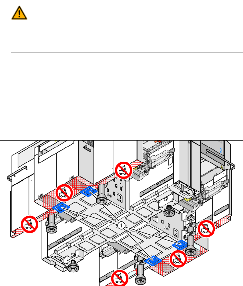
Fig. 4.5 - 26 Contact positions for the air cushion transport system
(1) Contact surfaces for the air cushion transport system
4 Setting Up and Commissioning User Manual SIPLACE CA
4.5 Setting Up the Placement Machine Edition 08/2011 EN
316
4.5.17 Final Adjustment of the Placement Machine
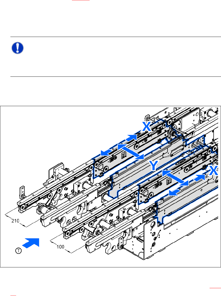
Place the machine spirit level in the X and Y directions, on the sides of the PCB conveyor in
placement area 1 (see fig. 4.5 - 27
). The PCB conveyor width is preset:
Single conveyor 210 mm
Dual conveyor, track 1 100 mm
Dual conveyor, track 2 210 mm 4
Note: 4
When using a dual conveyor, the spirit level for adjustment needs to be always placed on the
outer sides of the placement machine, when measuring in the X direction.
Measure the distance between the top edge of the PCB conveyor belt and the floor. This dis-
tance should be 800 mm, 900 mm, 930 mm or 950 mm.
4
Fig. 4.5 - 27 Adjusting the placement machine in the X and Y directions
Use an open-ended wrench SW36 to adjust the setting screw M24x2x120 (item 1 in fig. 4.5 -
28) so that the spirit level does not deviate from its zero point when measuring the required
PCB conveyor height.