00195941-03-UM SiplaceCA-EN.pdf - 第319页
User Manual SIPLACE CA 4 Setting Up and Commissioning Edition 08/2011 EN 4.5 Setting Up the Placement Machine 319 4.5.19 Removing the Corrosion Pr otection from the Guide Rails The placement mach ine is treated with a co…
4 Setting Up and Commissioning User Manual SIPLACE CA
4.5 Setting Up the Placement Machine Edition 08/2011 EN
318
4
NOTE 4
The tightening torque is 130 Nm. If you use a lower tightening torque, the placement machine
may tend to vibrate.
Unscrew the middle machine feet using a hook wrench 135 - 145 until they are seated firmly
on the ground.
Make sure that the middle machine feet are not unscrewed too far, otherwise they may mis-
align the placement machine.
4
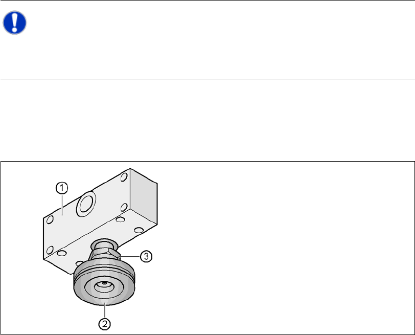
Fig. 4.5 - 29 Aligning and locking the middle machine foot
Recheck the exact alignment of the placement machine with the machine spirit level.
Use the size 65 open-ended spanner to tighten the M24 lock nut (item 3).
4.5.18 Removing the Shipping Braces
– Remove all the shipping braces from the gantry axes.
(1) Spacer
(2) Middle machine foot
(3) M24 lock nut

User Manual SIPLACE CA 4 Setting Up and Commissioning
Edition 08/2011 EN 4.5 Setting Up the Placement Machine
319
4.5.19 Removing the Corrosion Protection from the Guide Rails
The placement machine is treated with a corrosion protection agent before delivery.
CAUTION 4
– You should therefore remove the corrosion protection from all the axes and bearings when
you traverse the machine axes for the first time during commissioning.
– Grease all the axes and bearings with the grease described in the maintenance instructions.
If the corrosion protection agent is mixed with the bearing grease on the axes this can greatly re-
duce the service life of the bearings and guide rails.
CAUTION 4
Do not allow any alcohol to enter the guide carriages when you clean the guide rails and scale
rods. Alcohol will damage the bearing grease in the guide carriages.
4 Setting Up and Commissioning User Manual SIPLACE CA
4.6 Installing the SWS Edition 08/2011 EN
320
4.6 Installing the SWS
CAUTION 4
Before installing the SWS, make sure that the placement machine has been completely assem-
bled. (See section 4.5)
4.6.1 Warning Instructions
DANGER 4
Only ASM-technicians or certified persons may set up and start up the SWS.
Always follow the applicable accident prevention regulations.
During assembly or installation never lie down under the SWS. All assemblies and parts can
be fitted from above. If you still need to perform assembly work to the underside of the SWS,
take appropriate measures to secure the machine first. The fork-lift truck alone is not a suit-
able support!
Make sure that the gantries are positioned over the PCB conveyor area so that you do not
restrict your head movement during assembly, thus excluding the risk of injury.
You require two people to install the SWS:
– One person carries out the required assembly work.
– The other person monitors the stability of the lifted SWS during assembly.
Wear special safety boots to protect your feet.
Note:
Please note that the installation of an SWS is possible for: 4
– CA4 placement machine all locations (on the left-hand side for 1 and 3, on the right-hand side
for 2 and 4)