00195941-03-UM SiplaceCA-EN.pdf - 第322页
4 Setting Up and Commissioning User Manual SIPLACE CA 4.6 Installing the SWS Edition 08/2011 EN 322 4 Fig. 4.6 - 1 Connections on th e SWS 4 Push the forks of the fork-lif t truck under the SWS (see section 4.2.4.3 on …

User Manual SIPLACE CA 4 Setting Up and Commissioning
Edition 08/2011 EN 4.6 Installing the SWS
321
4.6.2 Tools and Equipment
You will need the following tools and equipment to install the SWS:
– Standard tool
– Torque wrench
– Fork-lift truck/hand lift (see section 4.3
), support bars
– Screwed feet
4.6.3 Installing the SWS in the Placement Machine
4.6.3.1 Position Fork Lift Truck
Position the fork-lift truck lengthwise under the SWS and open the forks until the contact sur-
faces of the SWS lie evenly on the forks. The magazine lift module must face the fork-lift truck.
WARNING 4
Before lifting the SWS, observe the following points to avoid causing irreversible damage to the
SWS:
– When lifting the SWS, make sure that the forks are loaded evenly. A firm support surface be-
tween the fork and the SWS prevents the SWS from tipping over when lifted. We recommend
that a second person monitors the lifting of the SWS and ensures that this does not tip over
to one side when lifted by the fork-lift truck.
4.6.3.2 Inserting the SWS in the Placement Machine
Note: 4
Before inserting the SWS, make sure that the CAN Bus connection X1x5 and X1x6, the com-
pressed air connection and the FFI communication interface W11 on the SWS are accessible.
4 Setting Up and Commissioning User Manual SIPLACE CA
4.6 Installing the SWS Edition 08/2011 EN
322
4
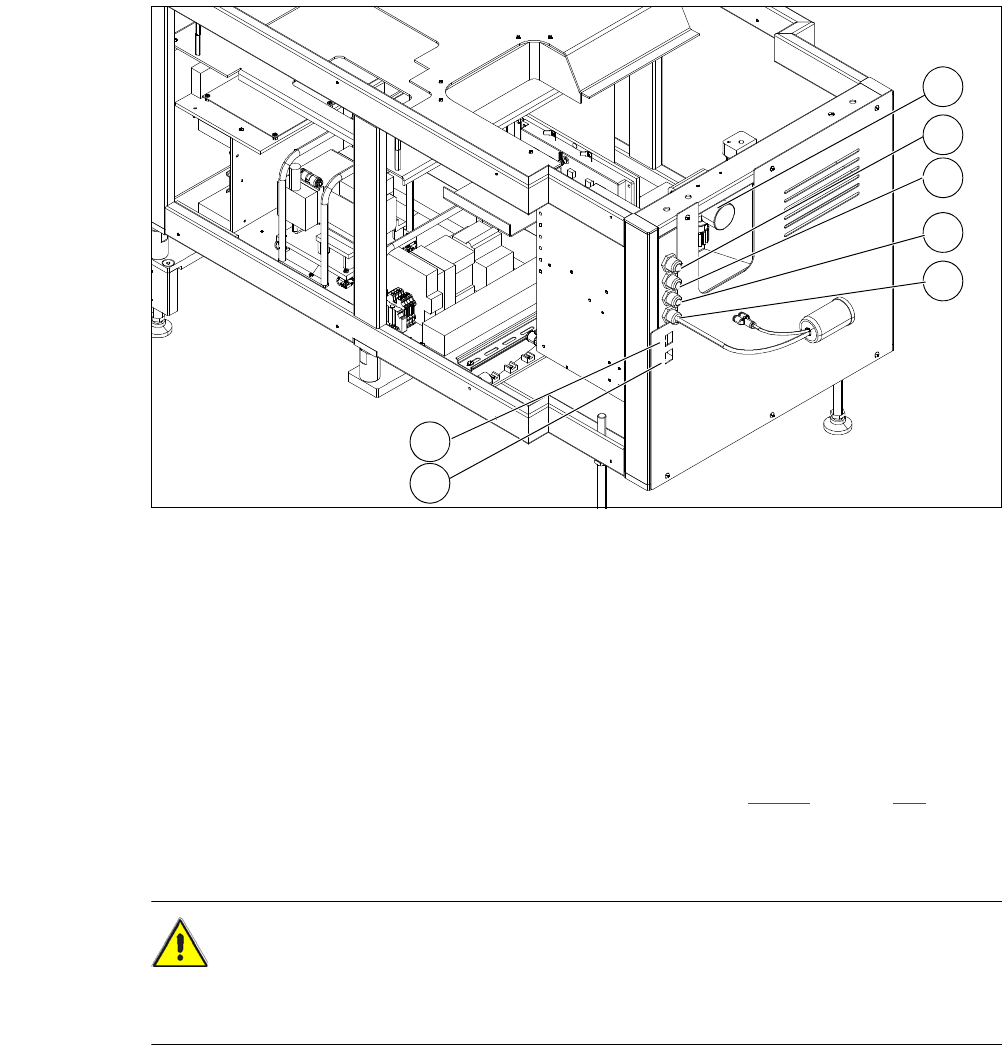
Fig. 4.6 - 1 Connections on the SWS
4
Push the forks of the fork-lift truck under the SWS (see section 4.2.4.3 on page 250).
Lift the SWS and align it to the placement machine. If the lifting range of the hand lift is not
sufficient, use wooden blocks or a similar object.
CAUTION 4
Before inserting the SWS into the machine, open the SWS monitor, so that this can not hit the
cover of the placement machine.
(1) Manometer for compressed air supply (2) Voltage supply
(3) Communication with SIPLACE machine (4) CAN bus
(5) Compressed air connection (modified
adapter dummy connector [03011592-01])
(6) LAN1
(7) LAN2
2
1
3
4
5
6
7
User Manual SIPLACE CA 4 Setting Up and Commissioning
Edition 08/2011 EN 4.6 Installing the SWS
323
Carefully push the SWS to approx. 30 cm before the bumper (see following figure) in the
placement machine (see following figure), so that you still have enough room to connect the
SWS and placement machine connections.
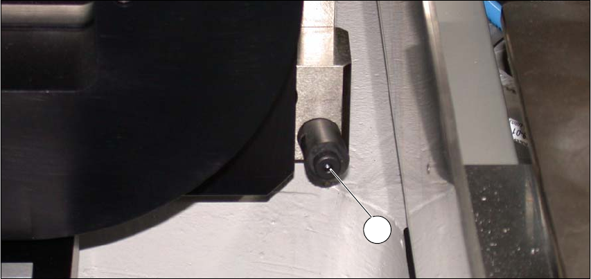
Fig. 4.6 - 2 Bumper
(1) Bumper
4.6.3.3 Connecting the SWS to the Placement Machine
The SWS connections need to be connected as follows to the placement machine:
– CAN Bus connections X1x6 and X1x5
– Compressed air connection to compressed air connection
– FFI communication interface W11 to FFI communication interface X1x3
1