00195941-03-UM SiplaceCA-EN.pdf - 第331页
User Manual SIPLACE CA 4 Setting Up and Commissioning Edition 08/2011 EN 4.8 Adapting the Length of th e SIPLACE X Used Tape Channel to the PCB Conveyor Heig ht 331 4.8 Adapting the Length of the SIPLACE X Used T ape Cha…
4 Setting Up and Commissioning User Manual SIPLACE CA
4.7 Adapting the SIPLACE X-Series Component Trolley to the PCB Conveyor Height Edition 08/2011 EN
330
4
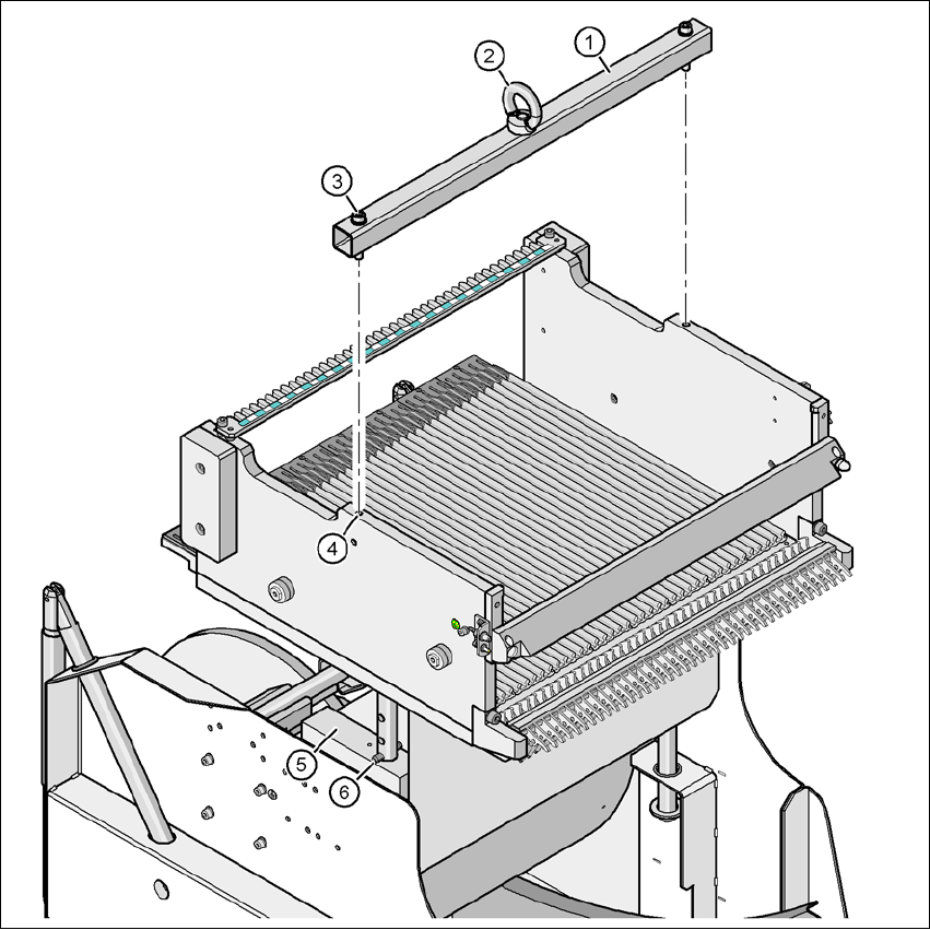
Fig. 4.7 - 2 fastening the assembly guide to the changeover table of the SIPLACE component trolley
(1) Mounting aid
(2) Eyelet
(3) Hexagon socket head screw DIN 912, M8 x 50, 2 x
(4) M8 threaded hole in the component table, 2x
(5) Supporting block, 2x
(6) Split pin, DIN 7343, 8 x 40 - St, 2 x
User Manual SIPLACE CA 4 Setting Up and Commissioning
Edition 08/2011 EN 4.8 Adapting the Length of the SIPLACE X Used Tape Channel to the PCB Conveyor Height
331
4.8 Adapting the Length of the SIPLACE X Used Tape
Channel to the PCB Conveyor Height
Depending on the PCB conveyor height, the length of the waste tape channel can be set so that
the pieces of tape are diverted directly into the waste tape bin of the component trolley.
4
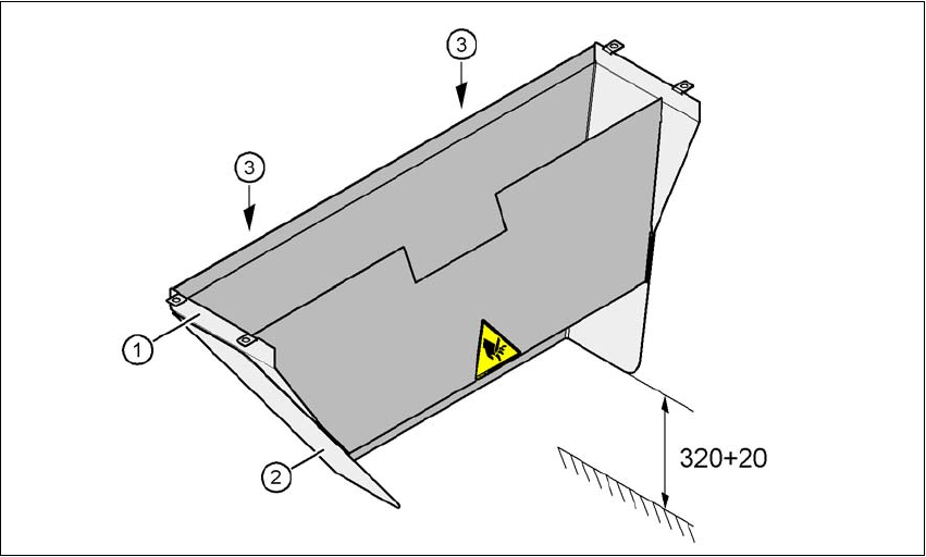
Fig. 4.8 - 1 Adapting the length of the used tape channel (X-series) - Dimensions in millimeters
(1) Used tape channel
(2) Extension
(3) Hexagonal nut M4, DIN 985, 2 x
4.8.1 Tools
– Fork wrench, size 7

4 Setting Up and Commissioning User Manual SIPLACE CA
4.8 Adapting the Length of the SIPLACE X Used Tape Channel to the PCB Conveyor Height Edition 08/2011 EN
332
4.8.2 Setting the Length of the Used Tape Channel
4.8.2.1 830 mm PCB Conveyor Height
Loosen the two hexagonal nuts M4 (item 3 in fig. 4.8 - 1).
Remove the extension (item 2 in fig. 4.8 - 1).
4.8.2.2 900 mm - 950 mm PCB Conveyor Heights
Loosen the two hexagonal nuts M4 (item 3 in fig. 4.8 - 1).
Adjust the extension (item 2 in fig. 4.8 - 1) so that the distance between the bottom edge and
the base does not exceed a maximum of 320 mm + 20 mm (see fig. 4.8 - 1
).