00195941-03-UM SiplaceCA-EN.pdf - 第350页
5 Tasks on the Mach ine User Manual SIPLACE CA 5.5 Configuring Feeders Edition 08/2011 EN 350 5.5 Configuring Feeders 5.5.1 Handling Feeders Feeder modules are prec ision devices. Y ou should therefore han dle the feeder…
User Manual SIPLACE CA 5 Tasks on the Machine
Edition 08/2011 EN 5.4 Performing Inspections
349
5.4.6 Using Spindles for Large Tape Reels
5
5
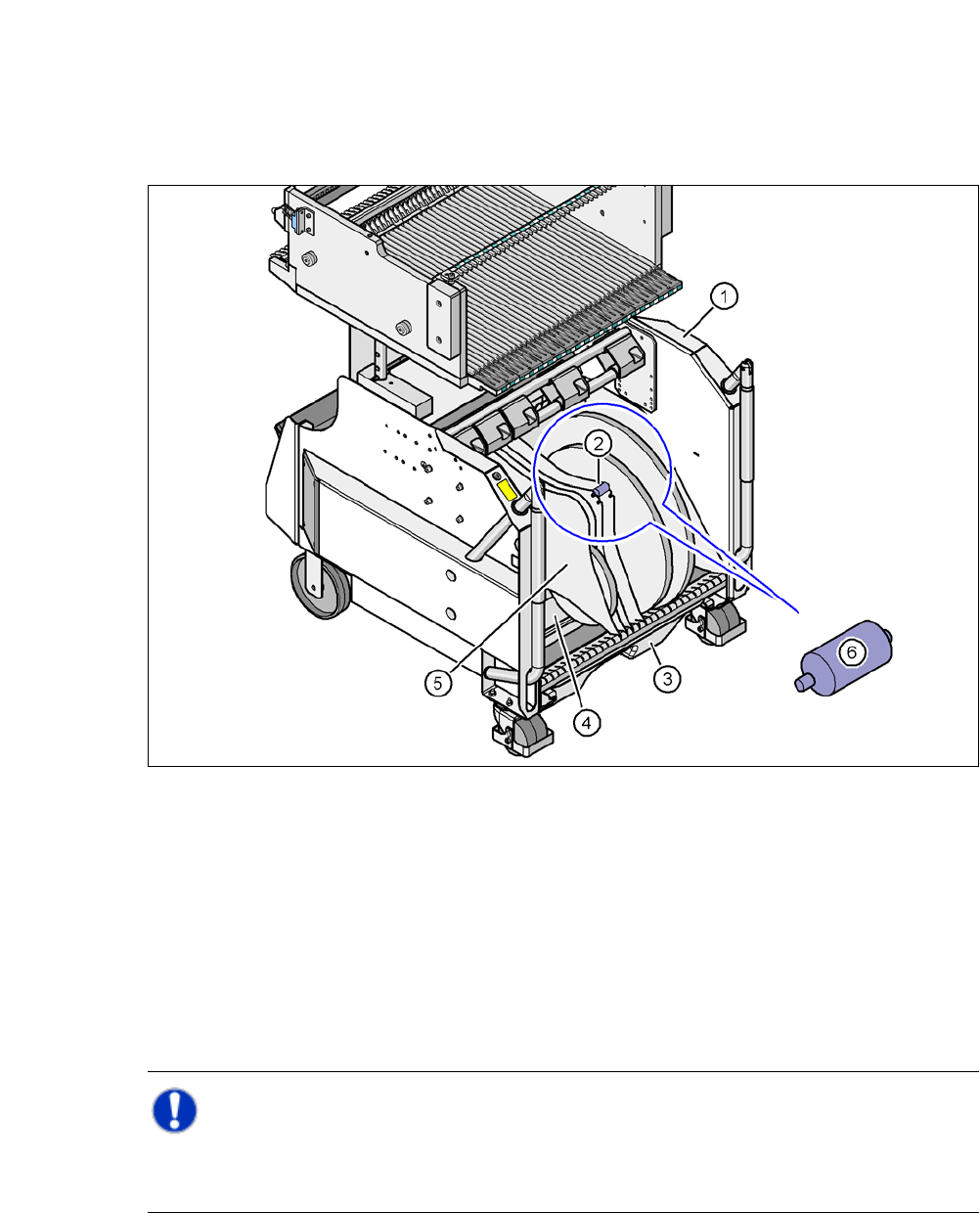
Fig. 5.4 - 4 Component trolley, SIPLACE X-series, with tape container and spindle
(1) Component trolley
(2) Position of the spindle
(3) Waste bin for unused tape
(4) Tape container
(5) Partition plate
(6) Spindle (enlarged)
Note: 5
X-series component trolleys do not generally need spindles. However, if the "Time-out" error
message occurs increasingly on the X feeder module, we recommend that you do use spindles.
5 Tasks on the Machine User Manual SIPLACE CA
5.5 Configuring Feeders Edition 08/2011 EN
350
5.5 Configuring Feeders
5.5.1 Handling Feeders
Feeder modules are precision devices. You should therefore handle the feeder modules with care.
Avoid bumping feeder modules into obstacles.
Do not drop the feeder modules.
Always use suitable tools for preventive maintenance.
5.5.2 Collect X-Feeder Modules from the Component Table
5
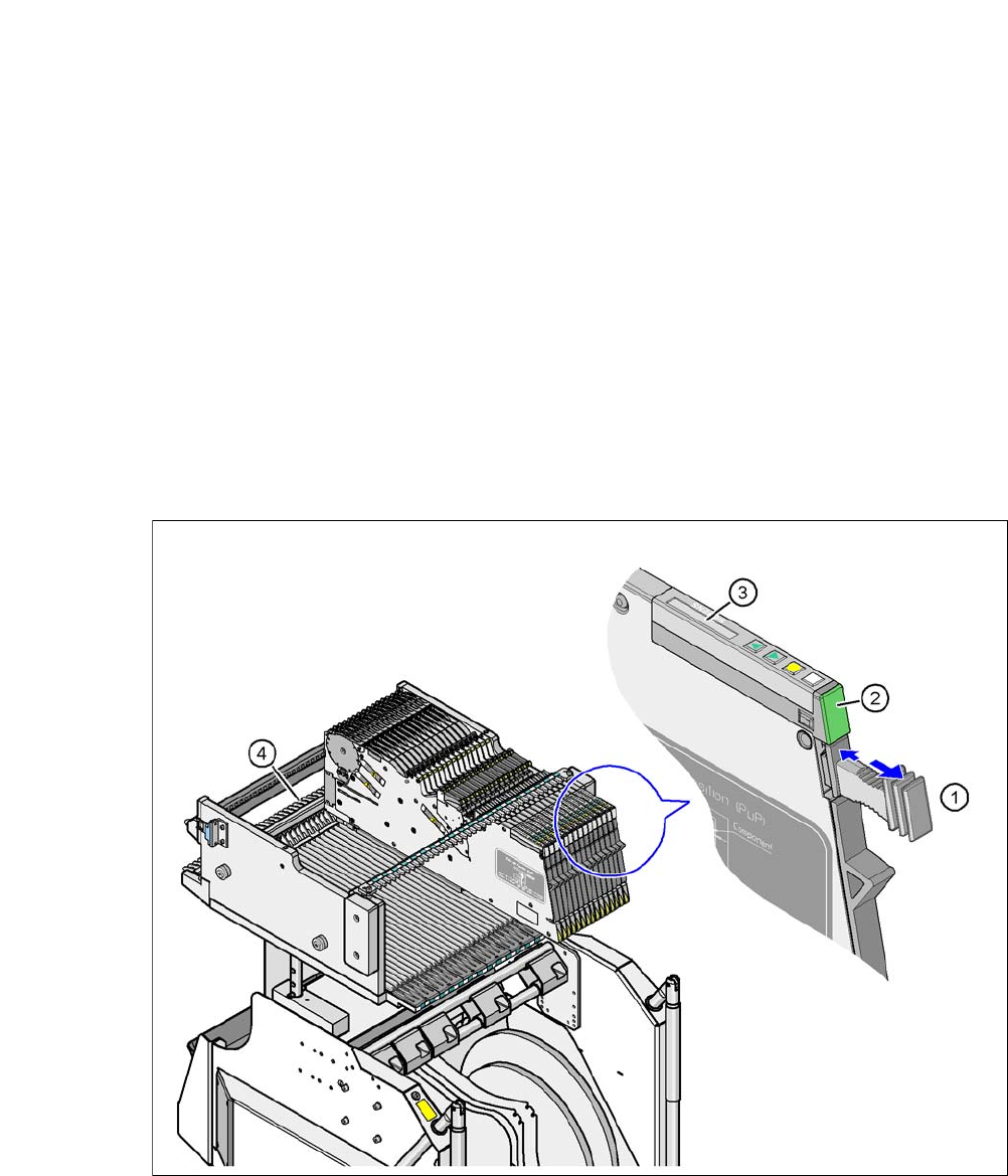
Fig. 5.5 - 1 Collect X-feeder modules from the component table
(1) Removal handle
(2) Status display
(3) LCD display
(4) Latch for locking the X feeder modules
User Manual SIPLACE CA 5 Tasks on the Machine
Edition 08/2011 EN 5.5 Configuring Feeders
351
When ready for operation, the status display (item 2 in fig. 5.5 - 1) shines green, provided the X
feeder is contained in the current setup. If the feeder module is not contained in the current setup,
the status display remains off.
The X feeder module is locked in position in the component table by a latch, and cannot be pulled
out. The procedure for removing feeder modules from the component table is as follows:
Press the removal handle (item 1 in fig. 5.5 - 1). The removal handle jumps out and the
status display goes out.
Wait roughly 1 second, until the lock (item 4 in fig. 5.5 - 1) releases the feeder.
Use the removal handle to pull the feeder module out of the component table. If you wait
longer than 5 seconds, the feeder module will be locked once more. The status display
will shine red and the LCD display (item 3 in fig. 5.5 - 1
) will show the message "Handle
--->>".
Engage the removal handle once more. If the X feeder module is contained in the current
setup, the status display lights up green and the track number and increment are appear
on the LCD display once more.
Press the removal handle again (item 1 in fig. 5.5 - 1) and pull the feeder out of the
changeover table.
5.5.3 Using the X Feeder Module on the Component Trolley (X Series)
5.5.3.1 Checking X-Feeder Module before Insertion
Check the following points before you use a feeder module on the component table:
The feeder module must be in perfect condition.
Gently tap the feeder, to make sure that the cover foil rocker (item 2 in fig. 5.5 - 2) does
not jam.
Check whether the pickup window area (item 3 in fig. 5.5 - 2) is free of loose components.
NOTE 5
Empty the component reject compartment (item 5 in fig.5.5 - 2
), before you shake the com-
ponents out of the feeder.
Press the lever (item 4 in fig. 5.5 - 2) to open the pickup window (item 3 in fig. 5.5 - 2) a
little, towards the front. This will raise the pickup window slightly.