00195941-03-UM SiplaceCA-EN.pdf - 第380页
6 Component and Die Handling User Manual SIPLACE CA 6.1 X Feeder Modules for the Component Trolley from the SIPLACE X Series Edition 0 8/2011 EN 380 6.1.1.5 Design of SIPLACE X Series T ape Feeders The two f ollowing dia…

User Manual SIPLACE CA 6 Component and Die Handling
Edition 08/2011 EN 6.1 X Feeder Modules for the Component Trolley from the SIPLACE X Series
379
6
The maximum height of the interfering edges above the upper edge ot the tape pocket is 3 mm.
Since the feeding modules do not posses any possibly standing up flaps and furthermore are
firmly anchored at the component table, the danger of a head crash is reduced to a minimum.
Tape feeder
modules
Feeder module width in
millimeters
Feeder module locations
required on the component
table
8 mm X 10,8 1
12 mm X 22,6 2
16 mm X 34,4 3
24 mm X 34,4 3
32 mm X 46,2 4
44 mm X 58,0 5
56 mm X 69,8 6
72 mm X 81,6 7
88 mm X 105,2 9
6 Component and Die Handling User Manual SIPLACE CA
6.1 X Feeder Modules for the Component Trolley from the SIPLACE X Series Edition 08/2011 EN
380
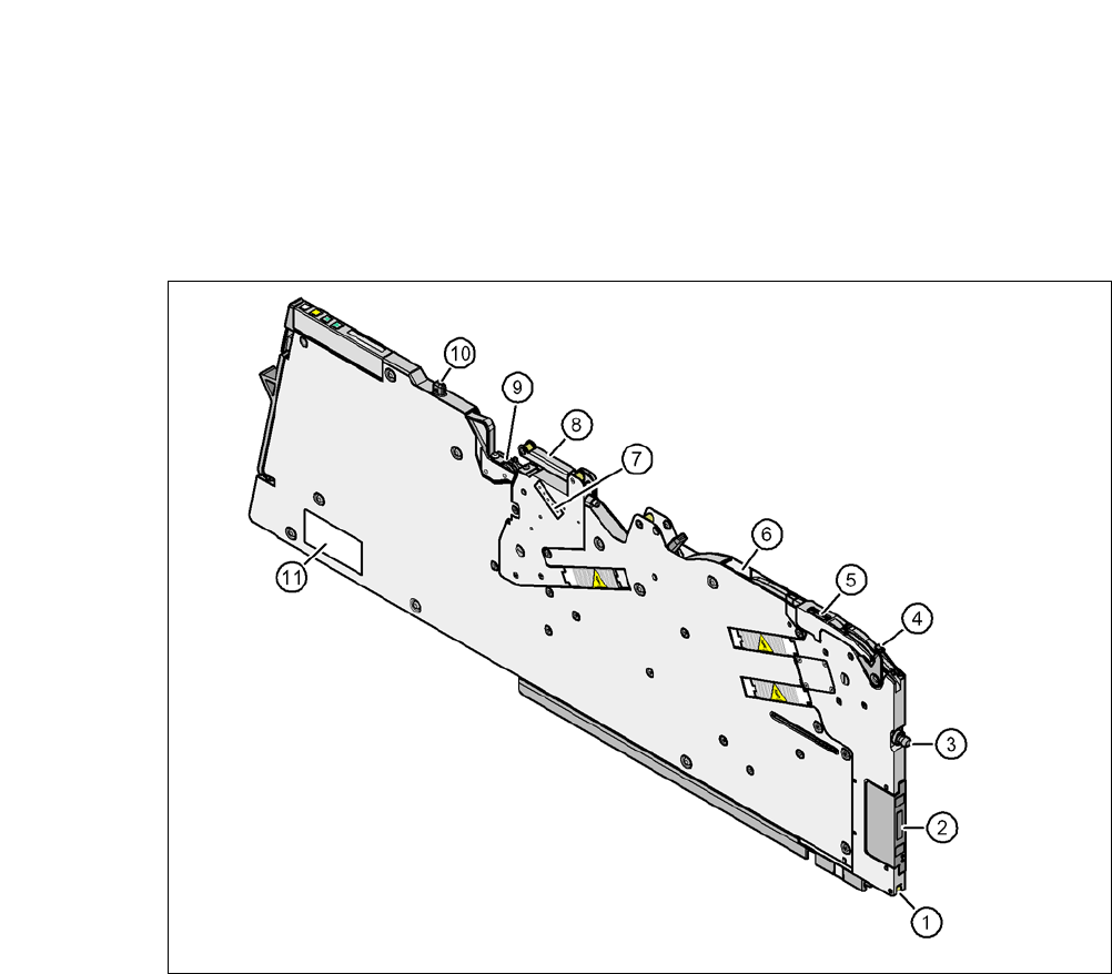
6.1.1.5 Design of SIPLACE X Series Tape Feeders
The two following diagrams show the design of the tape feeder module for the X-series with ref-
erence to the 8 mm X tape feeder module.
6
Fig. 6.1 - 1 8 mm X tape feeder module - front view
(1) Locking roller (the locking latch of the component table locks the feeder module in its end po-
sition with the locking roller.)
(2) EDIF (energy and data interface)
(3) Front centering pin
(4) Lever for raising the pickup window in order to thread in and remove the component tape
(5) Pickup window
(6) Outlet of the tape guide channel
(7) Setting the cover foil tension
(8) Cover foil rocker
(9) Cover foil packing wheels
(10)The back centering pin
(11) Type plate
User Manual SIPLACE CA 6 Component and Die Handling
Edition 08/2011 EN 6.1 X Feeder Modules for the Component Trolley from the SIPLACE X Series
381
6
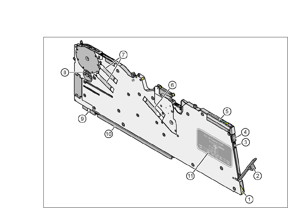
Fig. 6.1 - 2 8 mm X tape feeder module - back view
(1) Entry to the tape guide channel with tape spring
(2) Flap to cover foil container
(3) Integrated blade for cutting off the cover foil
(4) Removal handle, engaged
(5) Operating panel
(6) Drive motor for cover foil packing device
(7) Drive motors for tape transport
(8) Rotary valve for removing components
(9) Front slider guide
(10)Back slider guide
(11) Graphical representation of the pickup position in relation to the component size