00195941-03-UM SiplaceCA-EN.pdf - 第406页
6 Component and Die Handling User Manual SIPLACE CA 6.2 Component Trolley, SIPLACE X-Series Edition 08/2011 EN 406 6.2.4 Dimensions of the Compone nt T rolley , SIPLACE X Series 6 Fig. 6.2 - 5 Dimensions of the component…
User Manual SIPLACE CA 6 Component and Die Handling
Edition 08/2011 EN 6.2 Component Trolley, SIPLACE X-Series
405
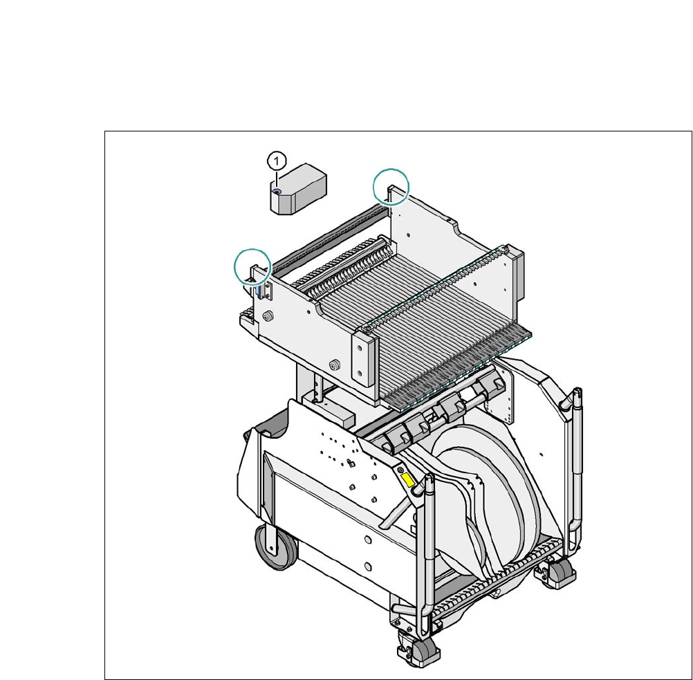
6.2.3 Fiducials at the SIPLACE X Series Component Trolleys
6
Fig. 6.2 - 4 Fiducials at the SIPLACE X series component trolleys
(1) Fiducials on the component trolley
Once the SIPLACE X-series component trolley has been docked in, the machine measures the
fiducials on the component trolley.
For components with an edge length of less than 0.5 mm, i.e. 0402 components and smaller, the
position of the component is determined with the tape pocket before the first component is picked
up.
6 Component and Die Handling User Manual SIPLACE CA
6.2 Component Trolley, SIPLACE X-Series Edition 08/2011 EN
406
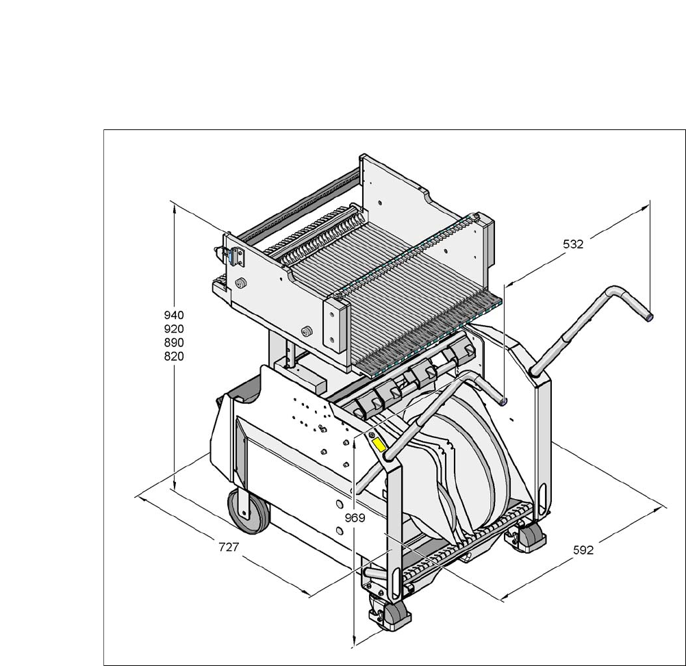
6.2.4 Dimensions of the Component Trolley, SIPLACE X Series
6
Fig. 6.2 - 5 Dimensions of the component trolley, SIPLACE X-series, all dimensions in millimeters
User Manual SIPLACE CA 6 Component and Die Handling
Edition 08/2011 EN 6.2 Component Trolley, SIPLACE X-Series
407
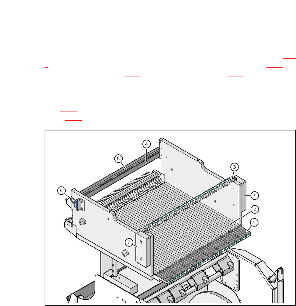
6.2.5 Component Table SIPLACE X-Series
The feeders are positioned with their front guiding slides onto the insertion aid (item 1 in fig. 6.2 -
6). When pushed inwards, the feeder slides with its guidances (item 12 and 13 in fig. 6.1 - 2) on
the guide profile (item 2 in fig. 6.2 - 6
) up to the stop bar (item 4 in fig. 6.2 - 6). A centering hole
(item 5 in fig. 6.2 - 6
) on the stop bar accommodates the front centering pin (item 4 in fig. 6.1 - 1)
of the X feeder. At the same time, the locking latch (item 1 in fig. 6.2 - 7
) of the changeover table
engages into the locking roller (item 1 in fig. 6.1 - 1
) of the feeder. The back centering pin (item 12
in fig. 6.1 - 1
) on the top of the feeder is accommodated by the recess in the centering bar (item
3 in fig. 6.2 - 6
).
6
Fig. 6.2 - 6 Component table, SIPLACE X-series, back view
(1) Insertion aid
(2) Guide profile ( profile)
(3) Centering bar for holding the "back" centering pin for X feeder modules
(4) Stop bar
(5) Centering holes
(6) Reed switch for the safety switch of the EMERGENCY STOP circuit
(7) Hand guard