00195941-03-UM SiplaceCA-EN.pdf - 第413页
User Manual SIPLACE CA 6 Component and Die Handling Edition 08/2011 EN 6.4 Used Tape Canne l - CO Trolley Docking Unit, SIPLACE X-Series 413 6.4 Used T ape Cannel - CO T rolley Docking Unit, SIPLACE X-Series 6.4.1 Partit…
6 Component and Die Handling User Manual SIPLACE CA
6.3 Used Tape Channel SIPLACE X Series Edition 08/2011 EN
412
6.3 Used Tape Channel SIPLACE X Series
6
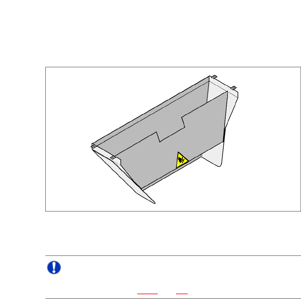
Fig. 6.3 - 1 Used tape channel for the component trolley docking unit from the SIPLACE X-series
Depending on the PCB conveyor height, the length of the waste tape channel can be set so that
the pieces of tape are diverted directly into the waste tape bin of the component trolley.
NOTE 6
The used tape channel for the X series can only be installed on the component trolley docking
unit of X series machines (see fig. 5.12 - 3, page 370).
User Manual SIPLACE CA 6 Component and Die Handling
Edition 08/2011 EN 6.4 Used Tape Cannel - CO Trolley Docking Unit, SIPLACE X-Series
413
6.4 Used Tape Cannel - CO Trolley Docking Unit,
SIPLACE X-Series
6.4.1 Partition Plate for Tape Pocket Heights up to 12 mm
In the standard version, the used tape channel can guide component tapes with a maximum
pocket height of 12 mm to the pneumatic tape cutter.
6
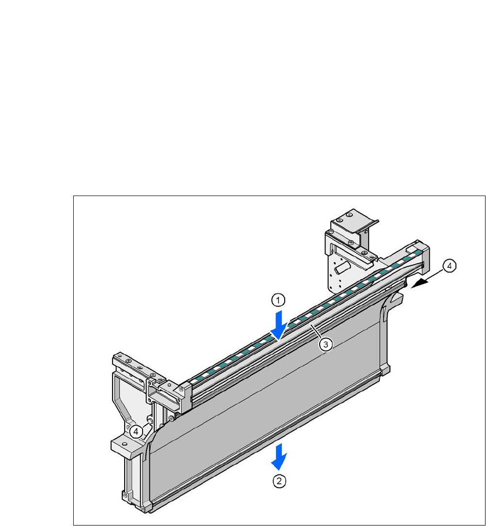
Fig. 6.4 - 1 Used tape channel, SIPLACE X-series
(1) Inlet slot for used tape
(2) Outlet slot for the used tape above the pneumatic tape cutter
(3) Dividing plate for tapes < 12 mm (can be removed for tapes > 12 mm)
(4) DIN 93384 screw - M4x20, 2x
6 Component and Die Handling User Manual SIPLACE CA
6.4 Used Tape Cannel - CO Trolley Docking Unit, SIPLACE X-Series Edition 08/2011 EN
414
6.4.2 Dismantling the Partition Plate for Tape Pocket Heights > 12 mm
If you use X feeder modules which process tape with a pocket height of > 12 mm, you will need
to remove the partition plate (item 3 in fig. 6.4 - 1
).
WARNING 6
Switch the placement machine off at the main switch to remove the dividing plate.
Disconnect the machine from the power and compressed air supply.
Secure the machine to prevent unauthorized reactivation, as described in section 2.12, page
111
.
Wait until the operating pressure for the tape cutter has dropped to 0 MPa.
Do not reach inside the used tape channel.
Loosen the two hexagonal screws (item 4 in fig. 6.4 - 1)
Pull out the dividing plate.
NOTE
Do not position feeder modules with shallow pockets immediately beside feeder modules with
deep pockets. The used tapes could overlap and build up.
6