00195941-03-UM SiplaceCA-EN.pdf - 第420页
6 Component and Die Handling User Manual SIPLACE CA 6.5 Docking Station for SIPLACE X Series Component Trolley Edition 08/2011 EN 420 6.5.5.1 T ools Y ou will need the following tools and equipment to adju st the height …
User Manual SIPLACE CA 6 Component and Die Handling
Edition 08/2011 EN 6.5 Docking Station for SIPLACE X Series Component Trolley
419
6.5.5 Adapting the Component Trolley Docking Unit to the PCB Conveyor Height
The X-series component trolley docking unit can be set to the following PCB conveyor heights with
just a few simple actions:
830 mm ± 15 mm (standard height)
900 mm ± 15 mm
930 mm ± 15 mm
950 mm ± 15 mm (SMEMA height)
6
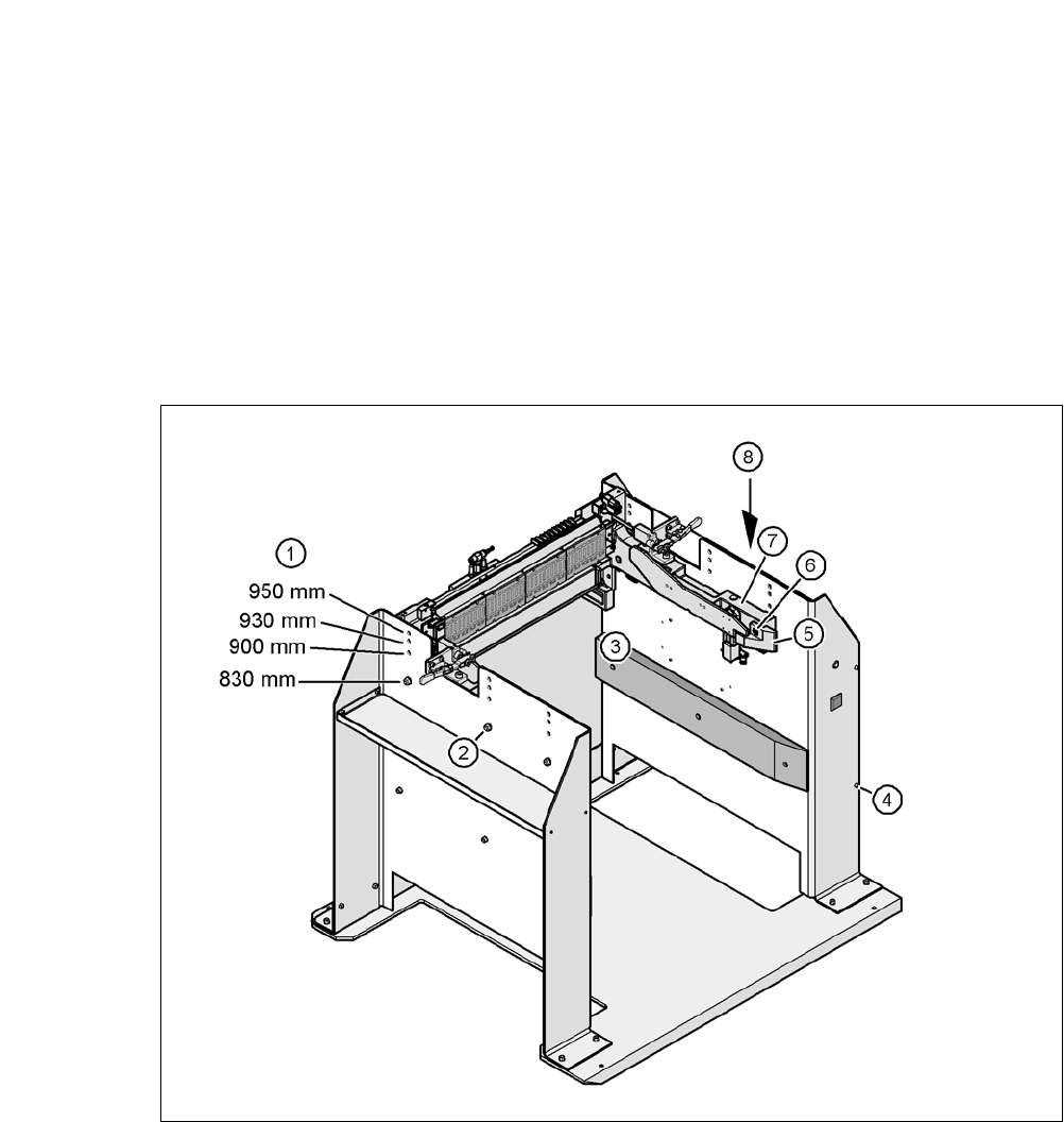
Fig. 6.5 - 4 Adapting the component trolley docking unit to the PCB conveyor heights
(1) Holes for the PCB conveyor height
(2) Hexagonal nut M8 and washer, 6x
(3) Hexagon socket head screw M8x40, 6x
(4) Hexagon socket head screw M5x12, 4x
(5) Guide
(6) Hexagon socket head screw M8x18, 2x
(7) Component trolley docking unit
(8) Panel
6 Component and Die Handling User Manual SIPLACE CA
6.5 Docking Station for SIPLACE X Series Component Trolley Edition 08/2011 EN
420
6.5.5.1 Tools
You will need the following tools and equipment to adjust the height for the component trolley
docking unit:
– Allen key, set
– Fork wrench, size 13
6.5.5.2 Adapting the Component Trolley Docking Unit to Other Heights
WARNING 6
Disconnect the docking station from the main power supply.
Disconnect the docking station from the compressed air supply
A second person will be needed to help with the conversion due to the weight of the component
trolley docking unit.
Loosen the two hexagon socket-head screws M8 x 18 (item 6 in fig. 6.5 - 4, page 419) and
remove the left-hand and right-hand guides (item 5 in fig. 6.5 - 4
).
6
Note: 6
Remove the covers (item 8 in fig. 6.5 - 4
) in the following cases only:
– You are converting the component trolley docking unit to a height of 830 mm.
– You are converting the component trolley docking unit from the height of 830 mm to a different
height.
Remove the 4 hexagon socket head screws M5x12. Hold the panel tightly so that it does not
drop down.
Remove the panel.
Loosen the 6 hexagon socket-head screws M8 (item 2 in fig. 6.5 - 4, page 419) and remove
the 6 washers.
Ask a second person to hold the component trolley docking unit, while you remove the 6
hexagon socket-head screws M8x40 (item 3 in fig. 6.5 - 4
).
Position the component trolley docking unit (item 7 in fig. 6.5 - 4) to the required height (item
1).
User Manual SIPLACE CA 6 Component and Die Handling
Edition 08/2011 EN 6.5 Docking Station for SIPLACE X Series Component Trolley
421
CAUTION 6
Be careful not to damage any cables while raising and lowering the component trolley docking
unit.
Insert the 6 hexagon socket-head screws M8x40 (item 3 in fig. 6.5 - 4) into the holes drilled
in the component trolley docking unit and docking station.
Fix the component trolley docking unit with the 6 M8 nuts and washers (item 2 in fig. 6.5 - 4,
page 419
).
Fasten the left and right guides (item 5 in fig. 6.5 - 4) with the hexagon socket-head screw
M8x18 (item 6 in fig. 6.5 - 4
).
If removed, refasten the covers (item 8 in fig. 6.5 - 4) with the 4 hexagon socket-head screws
M5x12.