00195941-03-UM SiplaceCA-EN.pdf - 第422页
6 Component and Die Handling User Manual SIPLACE CA 6.5 Docking Station for SIPLACE X Series Component Trolley Edition 08/2011 EN 422 6.5.6 Controls and Displays 6 Fig. 6.5 - 5 Docking station - Controls and d isplays
User Manual SIPLACE CA 6 Component and Die Handling
Edition 08/2011 EN 6.5 Docking Station for SIPLACE X Series Component Trolley
421
CAUTION 6
Be careful not to damage any cables while raising and lowering the component trolley docking
unit.
Insert the 6 hexagon socket-head screws M8x40 (item 3 in fig. 6.5 - 4) into the holes drilled
in the component trolley docking unit and docking station.
Fix the component trolley docking unit with the 6 M8 nuts and washers (item 2 in fig. 6.5 - 4,
page 419
).
Fasten the left and right guides (item 5 in fig. 6.5 - 4) with the hexagon socket-head screw
M8x18 (item 6 in fig. 6.5 - 4
).
If removed, refasten the covers (item 8 in fig. 6.5 - 4) with the 4 hexagon socket-head screws
M5x12.
6 Component and Die Handling User Manual SIPLACE CA
6.5 Docking Station for SIPLACE X Series Component Trolley Edition 08/2011 EN
422
6.5.6 Controls and Displays
6
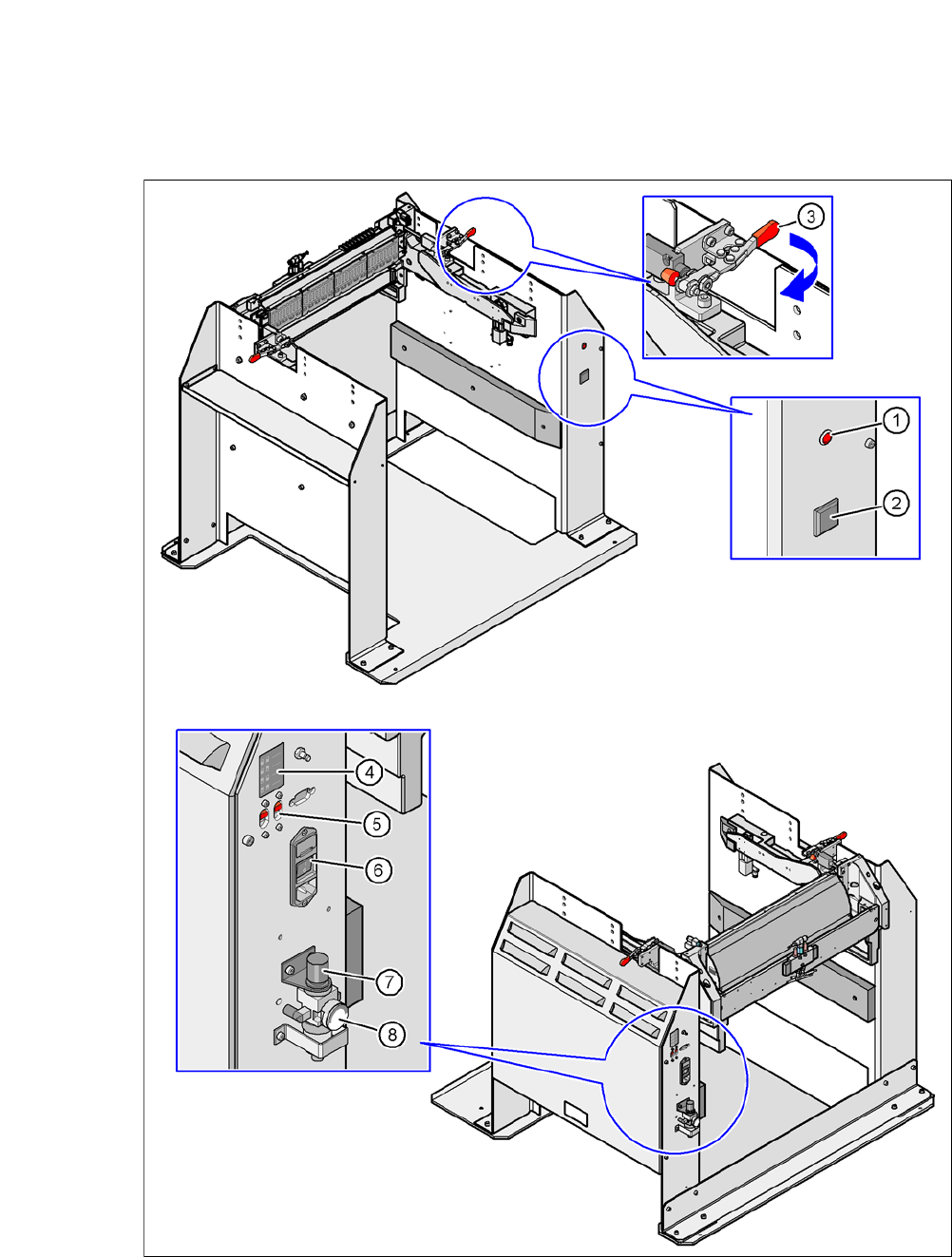
Fig. 6.5 - 5 Docking station - Controls and displays
User Manual SIPLACE CA 6 Component and Die Handling
Edition 08/2011 EN 6.5 Docking Station for SIPLACE X Series Component Trolley
423
Key to fig. 6.5 - 5
(1) Main power supply indicator lamp
(2) Button for locking and releasing all the feeder modules on the component trolley
(3) Horizontal tensioner for fixing the component table lever in the "closed" position
(4) Label showing switches S1 and S2 for CAN bus addressing
(5) Switches S1 and S2 for setting the CAN bus address
(6) Power switch
(7) Rotary knob for setting the operating pressure
(8) Manometer for displaying the operating pressure
6.5.7 Docking the SIPLACE X Series Component Trolley onto the Docking Station
WARNING 6
Only component trolleys from the SIPLACE X-series may be operated at this docking station.
While docking, do not reach into the areas between component trolley and docking station.
Open the two horizontal tensioners, by moving them in the direction of the arrow (item 3 in
fig. 6.5 - 5
, page 422).
Push the component trolley carefully into the docking station. This will raise the component
table.
Make sure that the component trolley is standing fully on the base plate of the docking station.
Close the two horizontal tensioners (item 3 in fig. 6.5 - 5, page 422.
The changeover table will be lifted to its final position and locked into place.
Use the button (item 2 in fig. 6.5 - 5) when you want to lock or unlock any of the feeders on
the changeover table.
6.5.8 Undocking the SIPLACE X Series Component Trolley from the Docking Sta-
tion
WARNING 6
While undocking, do not reach into the areas between component trolley and docking station.
Open the two horizontal tensioners (item 3 in fig. 6.5 - 5, page 422).
The component table is lowered.
Now pull the component trolley out of the docking station.