00195941-03-UM SiplaceCA-EN.pdf - 第429页
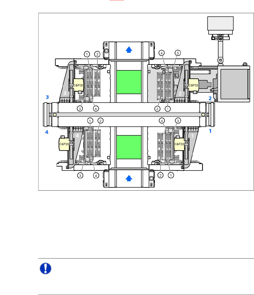
User Manual SIPLACE CA 7 Station Enlargements Edition 08/2011 EN 7.1 Nozzle Changer 429 7.1.2.2 Position of Nozzle Changer for C&P20 Head in CA3 Machine s Locations 1, 2, 3 and 4 can accommodate up to 2 nozzle change…
7 Station Enlargements User Manual SIPLACE CA
7.1 Nozzle Changer Edition 08/2011 EN
428
7.1.2.1 Position of Nozzle Changer for C&P20 Head in CA4 Machines
Locations 1, 2, 3 and 4 can accommodate up to 2 nozzle changers for the 20 segment Collect&
Place head (item 1 and 2 in fig. 7.1 - 4
). This gives a total capacity of 8 nozzle changers with 48
magazines and a total of 576 nozzle holders.
7
Fig. 7.1 - 4 Position of nozzle changers for 20 seg. Collect&Place CA head in CA4 machines
7
NOTE 7
When an SWS with a C&P20 nozzle changer is used, one row is installed by default. A second
row is available on request.
(1) Nozzle changer, "row 1"
(2) Nozzle changer, "row 2"
(3) Reject bin for components
(4) Take-off device and reject bin for nozzles
(5) Nozzle magazine
User Manual SIPLACE CA 7 Station Enlargements
Edition 08/2011 EN 7.1 Nozzle Changer
429
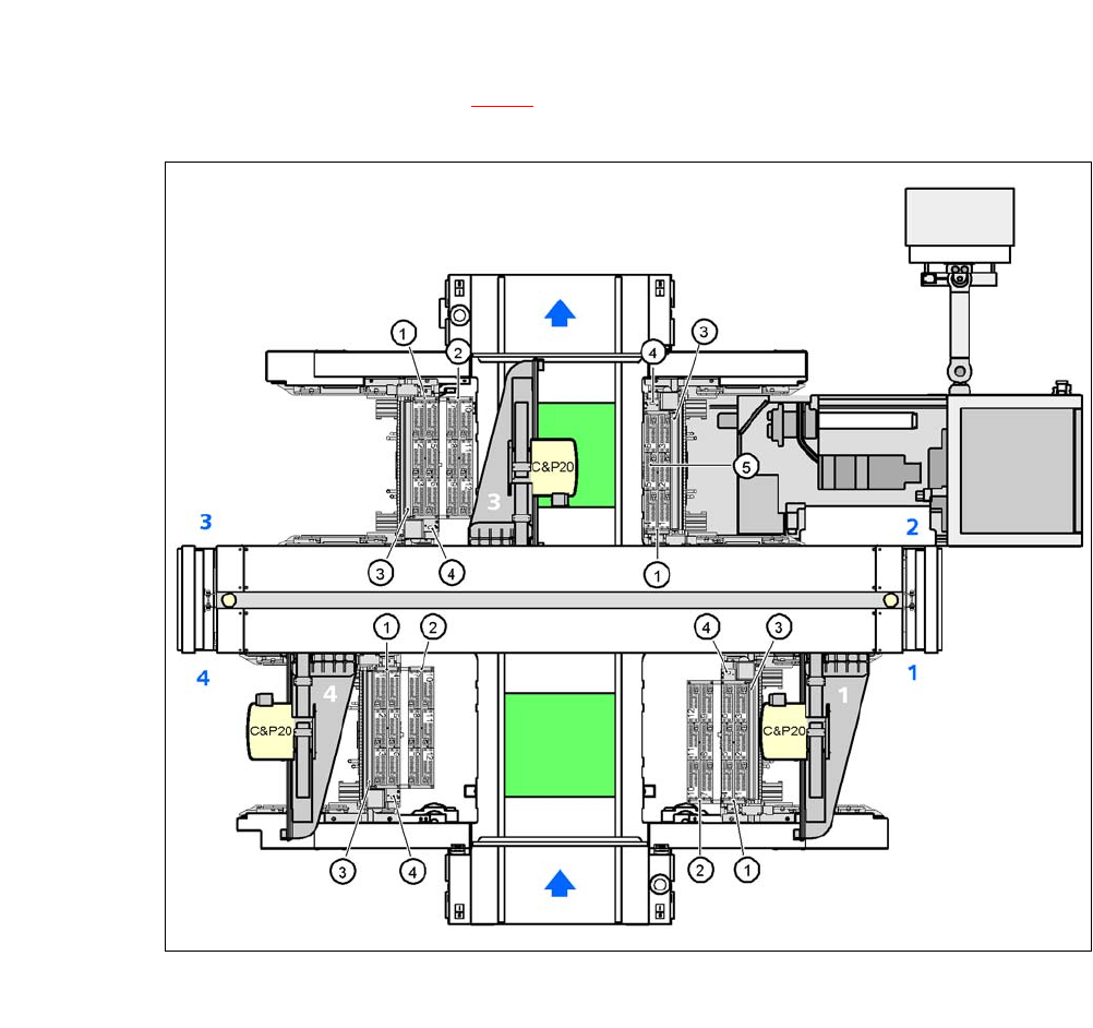
7.1.2.2 Position of Nozzle Changer for C&P20 Head in CA3 Machines
Locations 1, 2, 3 and 4 can accommodate up to 2 nozzle changers for the 20 segment Collect&
Place head (item 1 and 2 in fig. 7.1 - 5
). At location 2 no nozzle changer can be installed. This
gives a total capacity of 7 nozzle changers with 42 magazines and a total of 504 nozzle holders.
7
Fig. 7.1 - 5 Position of nozzle changers for 20 seg. Collect&Place CA head in CA3 machines
7
(1) Nozzle changer, "row 1"
(2) Nozzle changer, "row 2"
(3) Reject bin for components
(4) Take-off device and reject bin for nozzles
(5) Nozzle magazine
7 Station Enlargements User Manual SIPLACE CA
7.1 Nozzle Changer Edition 08/2011 EN
430
7.1.2.3 Technical Data
7
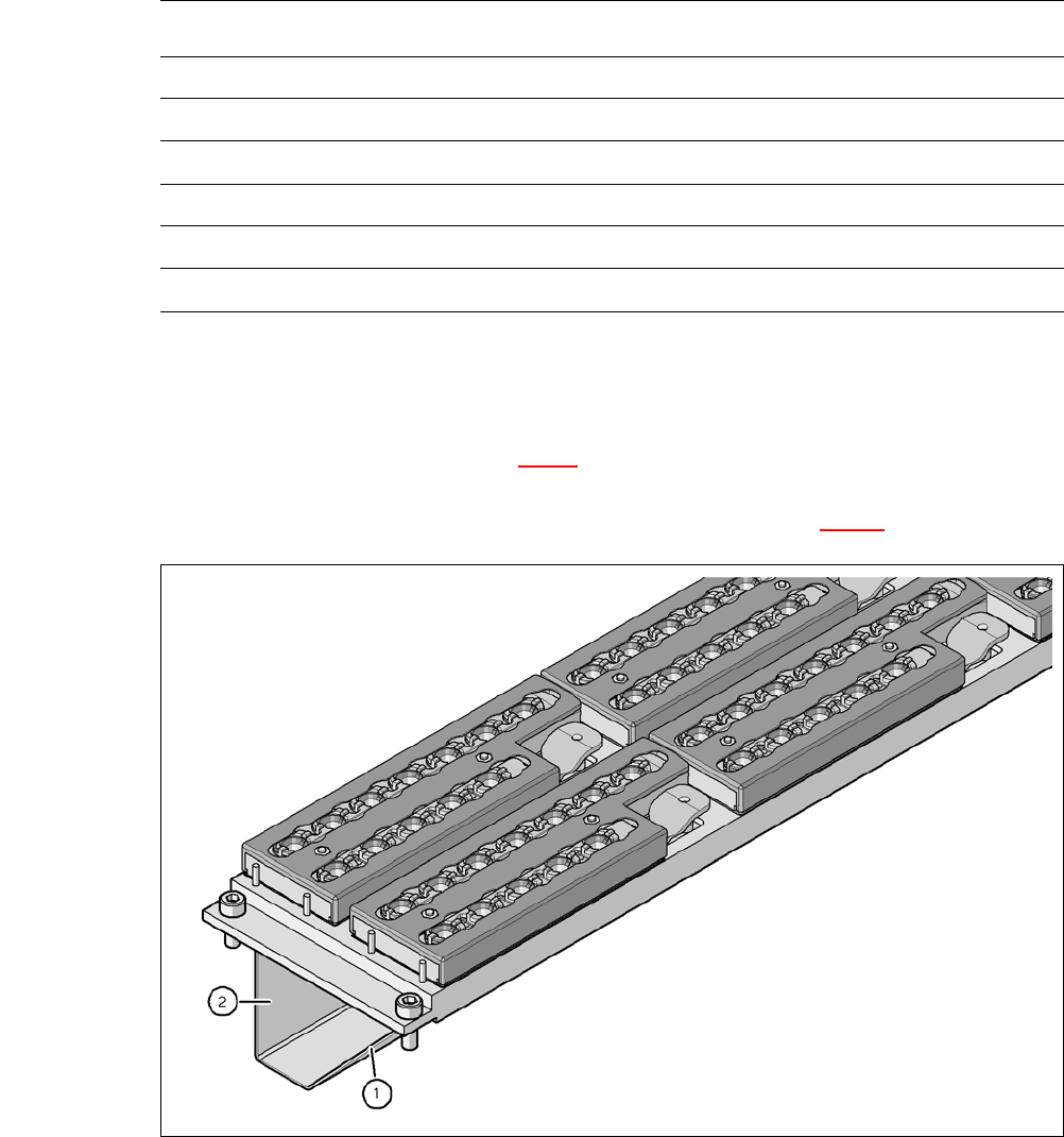
7.1.2.4 Assembly
The nozzle changers "row 1" (see fig. 7.1 - 4) are fixed to the component trolley docking units.
They are equipped with a take-off device and reject bin. There is an additional assembly kit for the
"row 2" nozzle changer, that can be ordered as an option (see section 7.1.2.9
).
7
Fig. 7.1 - 6 Assembly position
(1) Sloping side points towards the component trolley docking unit
(2) Vertical side points towards the PCB conveyor
Nozzle Changer for the 20 Segment Collect&Place CA Head
Dimensions (length x width x height) 449 x 94.5 x 79 mm³
Number of magazines 6 with 12 nozzle garages each
a
a) All 6 magazines have to be set up
Number of nozzle holders 72
Nozzle types 10xx, 11xx and 12xx
Nozzle changeover time approx. 2s per nozzle
Compressed air connection 0.48 MPa (4.8 bar)