00195941-03-UM SiplaceCA-EN.pdf - 第437页
User Manual SIPLACE CA 7 Station Enlargements Edition 08/2011 EN 7.1 Nozzle Changer 437 7.1.2.9 Nozzle Changer "Row 2" for the 20 Segment Co llect&Place CA Head [001 19716-xx] Nozzle changer 2 , X-serie, C&…
7 Station Enlargements User Manual SIPLACE CA
7.1 Nozzle Changer Edition 08/2011 EN
436
NOTE 7
– Move the locking plate into the "Magazine locked" position.
– Before inserting it, align the magazine so that the centering pins (item 2 and 6 in fig. 7.1 - 8
)
can slide into the centering holes and slot (item 6 in fig. 7.1 - 7).
Position the magazine on the pushbutton ball fixtures (item 5 in fig. 7.1 - 8).
Press the magazine down evenly so that the snap fastener balls engage in all the snap fas-
teners at the same time.
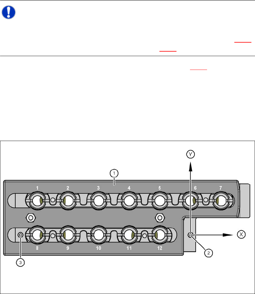
7.1.2.8 Position Detection
Each magazine of the nozzle changer has two fiducials: one for determining the position and one
for determining the angular position.
7
Fig. 7.1 - 9 Nozzle magazine - holder numbering, fiducials for determining the position and angular position
(1) Locking plate in position "magazine open"
(2) Fiducial for determining the position
(3) Fiducial for determining the angular position
User Manual SIPLACE CA 7 Station Enlargements
Edition 08/2011 EN 7.1 Nozzle Changer
437
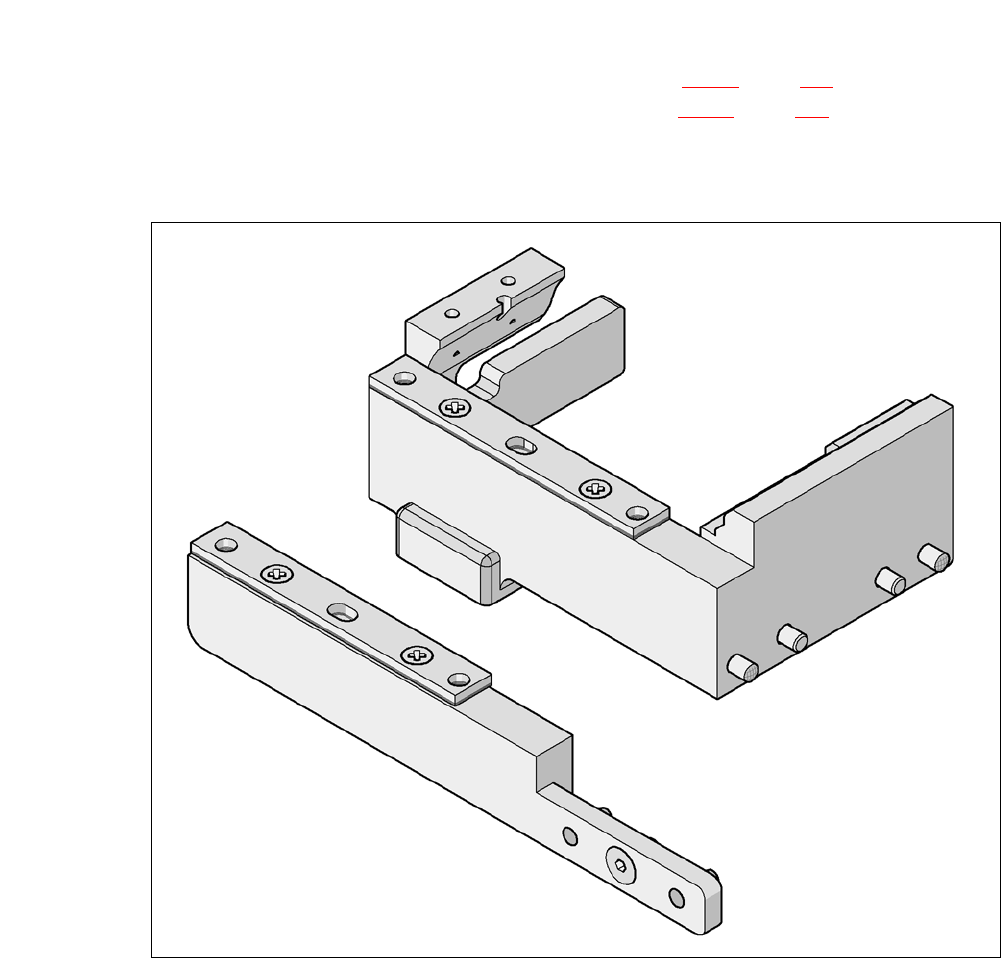
7.1.2.9 Nozzle Changer "Row 2" for the 20 Segment Collect&Place CA Head
[00119716-xx] Nozzle changer 2, X-serie, C&P20
lThe nozzle changer "Row 2" can be installed at the following locations, if no SWS is installed:
CA4 machine: locations 1, 2, 3 and 4 (see fig. 7.1 - 4
, page 428)
CA3 machine: Locations 1, , 3 and 4 (see fig. 7.1 - 5
, page 429)
The retrofit package contains appart from the the nozzle changer an assembly kit.
7
Fig. 7.1 - 10 Assembly kit for the nozzle changer "Row 2"
7
7
7 Station Enlargements User Manual SIPLACE CA
7.1 Nozzle Changer Edition 08/2011 EN
438
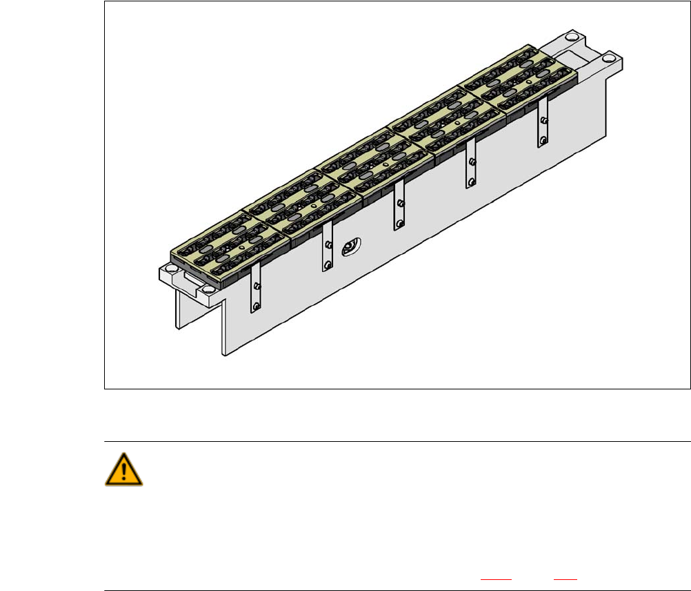
7.1.3 Nozzle Changer for the 12 Segment Collect&Place CA Head
[00119661-xx]Nozzle changer HF/X/CA/D3, 12 segment C&P head
This nozzle changer can hold up to 5 magazines, each with 12 nozzle holders. The magazines
are seated on a common support. They are centered using two parallel pins and fixed in place with
clips.
7
Fig. 7.1 - 11 Nozzle changer for the 12 segment Collect&Place CA head
WARNING 7
Only install the associated nozzle changer for each placement head. There is a risk of head
crashes with mixed configurations.
Only use reject bins marked [03003719-06]. Otherwise there is a risk of collision with the com-
ponent sensor of the C&P20 placement head (see section 2.6.9, page 76).