00195941-03-UM SiplaceCA-EN.pdf - 第447页
User Manual SIPLACE CA 7 Station Enlargements Edition 08/2011 EN 7.1 Nozzle Changer 447 7.1.3.9 Nozzle Changer "Row 2" for the 12 Segment Co llect&Place CA Head [001 19663-xx] Nozzle changer 2 HF/X/C A/D3, …
7 Station Enlargements User Manual SIPLACE CA
7.1 Nozzle Changer Edition 08/2011 EN
446
NOTE
The magazine must be inserted so that the centering pins can slide into the centering hole
(item 3 in fig. 7.1 - 16) and slot (item 4 in fig. 7.1 - 16). 7
First place the side of the magazine with the numbered nozzles 1, 2, 3 and 4 on the base.
The retaining clamp (item 2 in fig. 7.1 - 16
) must slide into the magazine slit.
Push the spring hook away from the magazine.
Press the magazine so that it lies flat on the base, then release the spring hook. The spring
hook must latch into place.
7.1.3.8 Position Detection
Every magazine of the nozzle changer has a positioning fiducial for position detection.
7
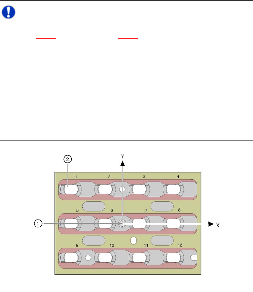
Fig. 7.1 - 17 Nozzle changer - Position detection
(1) Position fiducial
(2) Position of the nozzles in the magazine in relation to the position fiducial
User Manual SIPLACE CA 7 Station Enlargements
Edition 08/2011 EN 7.1 Nozzle Changer
447
7.1.3.9 Nozzle Changer "Row 2" for the 12 Segment Collect&Place CA Head
[00119663-xx] Nozzle changer 2 HF/X/CA/D3, 12 segment Collect&Place head
The "row 2" nozzle changer may be installed at the following locations:
CA4 machine: locations 1, 2, 3 and 4 (see fig. 7.1 - 12
, page 439)
CA3 machine: Locations 1, , 3 and 4 (see fig. 7.1 - 13
, page 440)
The retrofit package contains the nozzle changer and an assembly kit.
7
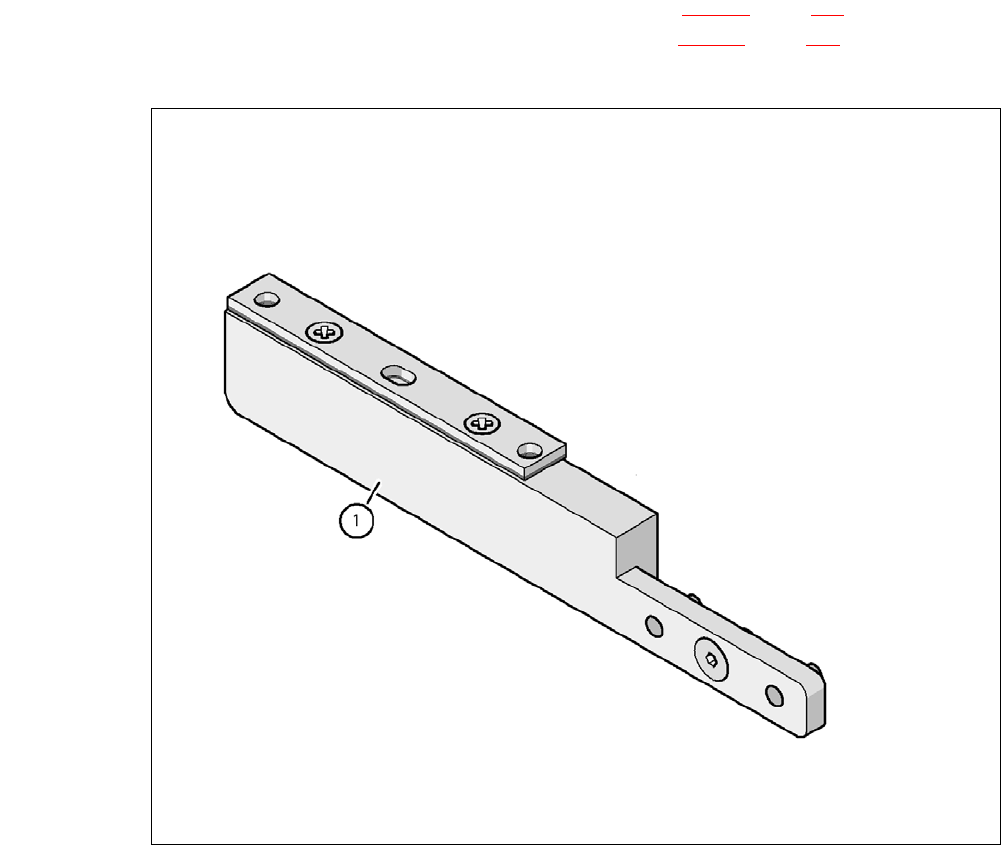
Fig. 7.1 - 18 Assembly kit for the nozzle changer "Row 2"
(1) Assembly kit for the nozzle changer "Row 2"
7 Station Enlargements User Manual SIPLACE CA
7.1 Nozzle Changer Edition 08/2011 EN
448
7.1.4 Nozzle Changer for the 6 Segment Collect&Place CA Head
[00119662-xx]Nozzle changer HF/X/CA/D3, 6 segment Collect&Place head
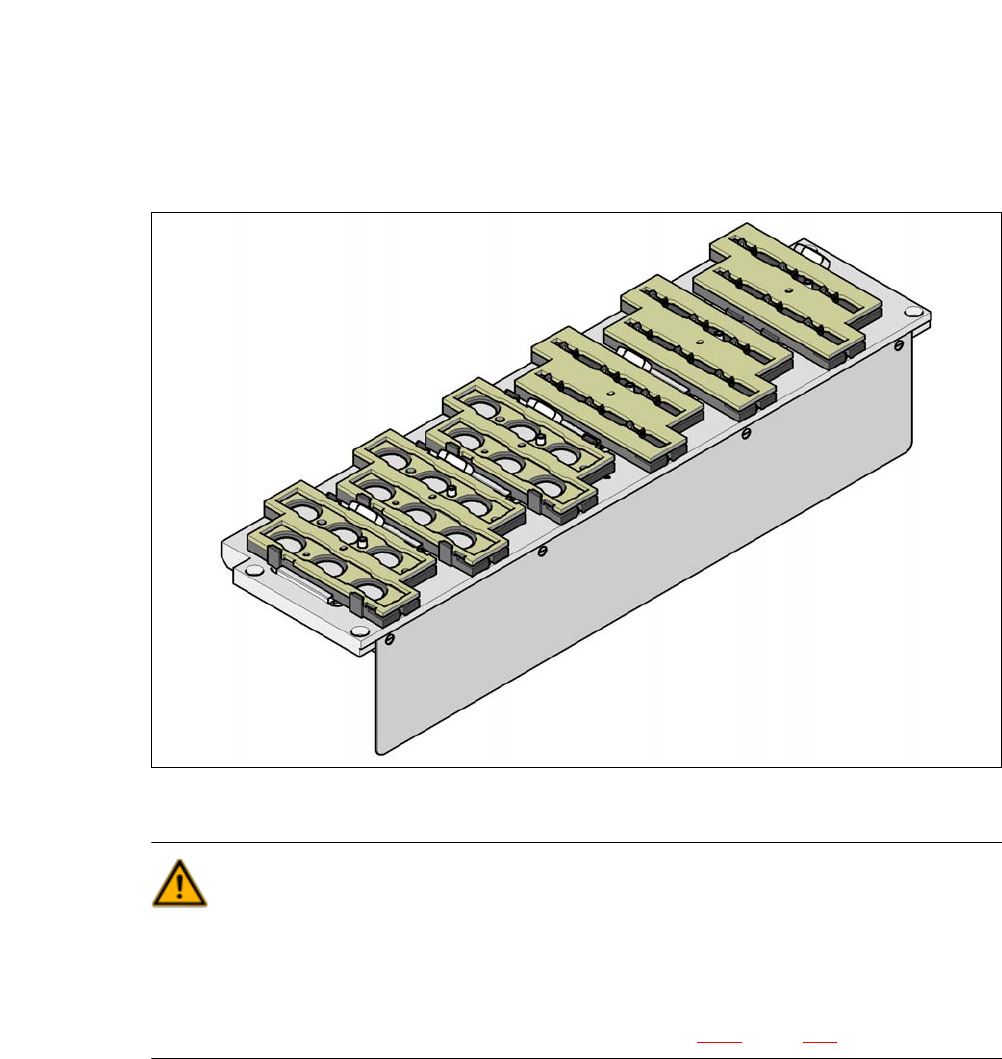
This nozzle changer can hold up to 6 magazines, each with 6 nozzle holders. There are 2 maga-
zines available: magazines for nozzles of type 8xx and magazines for nozzles of type 9xx. The
magazines are seated on a common support. They are centered using two parallel pins and fixed
in place with clips.
7
Fig. 7.1 - 19 Nozzle changer for the 6 segment Collect&Place CA head
WARNING 7
Only install the associated nozzle changer for each placement head. There is a risk of head
crashes with mixed configurations.
Only use reject bins marked [03003719-06]. Otherwise there is a risk of collision with the com-
ponent sensor of the C&P20 placement head (see section 2.6.9, page 76).