00195941-03-UM SiplaceCA-EN.pdf - 第453页
User Manual SIPLACE CA 7 Station Enlargements Edition 08/2011 EN 7.1 Nozzle Changer 453 7 Fig. 7.1 - 23 Magazine and nozzle holders (1) Position fiducial (2) Lockin g plate (3) Nozzle garage for nozzles of type 9xx and 8…
7 Station Enlargements User Manual SIPLACE CA
7.1 Nozzle Changer Edition 08/2011 EN
452
7.1.4.5 Functional Description
The nozzles are located in nozzle garages and are fixed by a movable locking plate. A pneumatic
cylinder moves the locking plate by 12 mm. Depending on the position of the locking plate, all noz-
zles are either clamped into place or released. The default position of the locking plate, i.e. if there
is no nozzle change in progress, is "closed".
Every magazine of the nozzle changer has a positioning fiducial for position detection. The mag-
azine locations are numbered from 1-6 for the nozzle changers of "row 1" and from 7-12 for the
"row 2" nozzle changers (see fig. 7.1 - 20
). The 6 nozzle garages in the magazines are also num-
bered consecutively (see fig. 7.1 - 23
).
NOTE 7
Special magazines can be made after consulting with ASM Assembly Systems GmbH & Co.KGa
and receive a seperate marking.
Nozzle Pick Up 7
– The Z-axis of the Collect&Place CA head moves downwards.
– The locking plate (item 2 in fig. 7.1 - 23
, page 453) opens and releases the nozzles.
– The nozzle is taken up by the sleeve of the Collect&Place CA head.
– The Z axis moves up.
Placing a Nozzle Down 7
– The locking plate (item 2 in fig. 7.1 - 23, page 453) opens and releases the nozzles.
– The Z-axis of the Collect&Place CA head moves downwards and places the nozzle down.
– The locking plate closes.
– The Z-axis of the Collect&Place CA head moves upwards.
Rejecting Defective Nozzles 7
– At the reject unit (item 4 in fig. 7.1 - 20) the Z-axis of the Collect&Place CA head moves down-
wards by 14 mm and transfers the defective nozzle to the hole of the reject unit.
– The Z axis moves up again and the nozzle is stripped from the sleeve by spring wires.
– The nozzle drops into the reject bin.
User Manual SIPLACE CA 7 Station Enlargements
Edition 08/2011 EN 7.1 Nozzle Changer
453
7
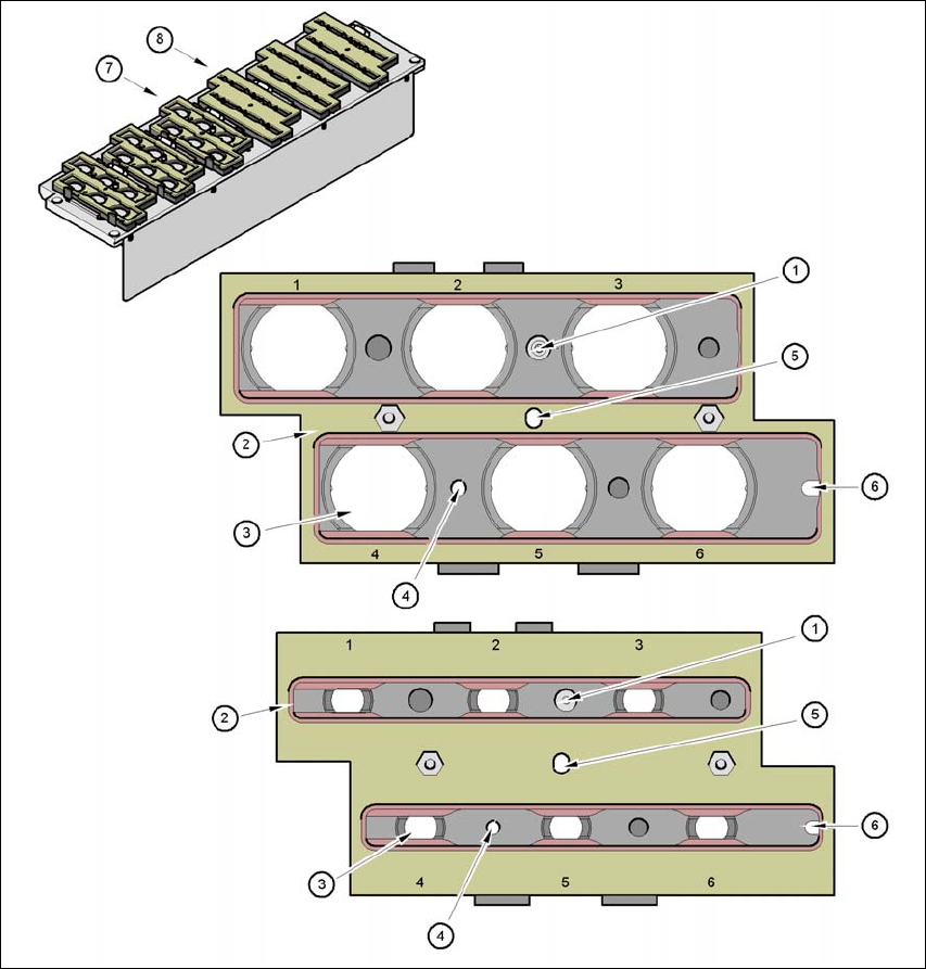
Fig. 7.1 - 23 Magazine and nozzle holders
(1) Position fiducial
(2) Locking plate
(3) Nozzle garage for nozzles of type 9xx and 8xx
(4) Hole for cylinder pin to center the magazine
(5) Hole for cylinder pin of the push mechanism
(6) Longhole for cylinder pin to center the magazine
(7) Magazine for
type 8 xx nozzles
(8) Magazine for type 9 xx nozzles
7 Station Enlargements User Manual SIPLACE CA
7.1 Nozzle Changer Edition 08/2011 EN
454
7.1.4.6 Operation
Within a nozzle family, you can fill magazines with different nozzle types: 8 series magazines,
for example, can be filled with nozzles of type 821, 822, 823, and 9 series magazines with
nozzles of type 911, 914 etc.
NOTE 7
Fill the magazines off the machine and always replace complete magazines. 7
Open the locking plate and place the nozzles in the nozzle holders.
Close the locking plate so that the nozzles cannot drop out of the magazines.
CAUTION 7
Magazines may only be filled if all the nozzles on the Collect&Place CA head have been
placed back in their magazines. 7
Programming the nozzle changer is described in the SIPLACE Pro user manual.
NOTE 7
Avoid letting components drop onto the magazines. This can cause the locking plate to jam.
Avoid letting components drop onto the free locations of the feeders. The components could
stick to the magnetic strips. Production may have to be interrupted if the feeder modules are
not placed on the component table correctly. You should therefore regularly clean the maga-
zines and free locations.