00195941-03-UM SiplaceCA-EN.pdf - 第463页
User Manual SIPLACE CA 7 Station Enlargements Edition 08/2011 EN 7.4 Component C amera for the TwinHead, FC Camer a 463 7.4 Component Camera for the T winHead, FC Camera 7.4.1 St ationary P&P compone nt camera (type …

7 Station Enlargements User Manual SIPLACE CA
7.3 SIPLACE High-Force Head Edition 08/2011 EN
462
7.3 SIPLACE High-Force Head
[00119734-xx]High force head for X series
This item number only applies when a new placement machines is ordered with a High-
Force Head rather than a standard TwinHead. 7
[00119753-xx] High force upgrade kit
Use this item number if you want to replace a standard TwinHead with a High-Force Head.7
7.3.1 General
The SIPLACE high-force head is an advanced development of the standard TwinHead. It can pro-
cess the same component range and also offers the possibility of achieving set-down forces up to
30 N.
All other technical data are the same for the TwinHead and the high-force head (see section
3.8.6.3
, page 207).
All the nozzles and grippers that are used with the standard TwinHead can be used for the SI-
PLACE High-Force Head.
Programmable set-down force 2.0 N to 10 N ± 10 %
greater than 10 N up to 30 N ± 15 %
User Manual SIPLACE CA 7 Station Enlargements
Edition 08/2011 EN 7.4 Component Camera for the TwinHead, FC Camera
463
7.4 Component Camera for the TwinHead, FC Camera
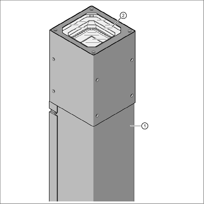
7.4.1 Stationary P&P component camera (type 25) 16 x 16, digital (FC camera)
[00119718-xx]Component camera, stationary 16x16 digital, type 25
7
Fig. 7.4 - 1 Stationary P&P component camera (type 25) 16 x 16, digital (FC camera)
(1) Camera housing with integral camera and camera amplifier
(2) Glass plate - illumination and lens below
7
7 Station Enlargements User Manual SIPLACE CA
7.4 Component Camera for the TwinHead, FC Camera Edition 08/2011 EN
464
7.4.2 Technical Data
7
7
7
7
7.4.3 Position of the Stationary Component Cameras
The position of the stationary component camera and the corresponding configuration are de-
scribed in section 3.13.1
, from page 224 onwards.
7.4.4 Safety Instructions for the TwinHead Component Cameras during
a Placement Head Change
WARNING 7
During a placement head change from TwinHead to Collect&Place CA head, the component
cameras (stationary P&P, type 33, 55 x 45, and type 25, 16 x 16) for the TwinHead must be dis-
mantled, otherwise the Collect&Place CA head will collide with the camera housings.
Component dimensions 0,2 mm x 0,2 mm to 16 mm x 16 mm during simple measurement of
the component
Range of components 0402 to SO, PLCC, QFP, sockets, plugs, BGA, special components,
bare dies, flip-chips, shields
Min. lead pitch 0.25 mm
Min. lead width 0.1 mm
Min. ball pitch 0.14 mm
Min. ball diameter 0.08 mm
Field of vision 19,4 mm x 19,4 mm
Illumination method Front-illumination (6 levels, programable as required)