00195941-03-UM SiplaceCA-EN.pdf - 第465页
User Manual SIPLACE CA 7 Station Enlargements Edition 08/2011 EN 7.5 PCB Camera Multicolor, Type 24, Digital 465 7.5 PCB Camera Multicolor , T ype 24, Digit al 7.5.1 Structure [001 19774-xx]PCB camera, X series, multicol…

7 Station Enlargements User Manual SIPLACE CA
7.4 Component Camera for the TwinHead, FC Camera Edition 08/2011 EN
464
7.4.2 Technical Data
7
7
7
7
7.4.3 Position of the Stationary Component Cameras
The position of the stationary component camera and the corresponding configuration are de-
scribed in section 3.13.1
, from page 224 onwards.
7.4.4 Safety Instructions for the TwinHead Component Cameras during
a Placement Head Change
WARNING 7
During a placement head change from TwinHead to Collect&Place CA head, the component
cameras (stationary P&P, type 33, 55 x 45, and type 25, 16 x 16) for the TwinHead must be dis-
mantled, otherwise the Collect&Place CA head will collide with the camera housings.
Component dimensions 0,2 mm x 0,2 mm to 16 mm x 16 mm during simple measurement of
the component
Range of components 0402 to SO, PLCC, QFP, sockets, plugs, BGA, special components,
bare dies, flip-chips, shields
Min. lead pitch 0.25 mm
Min. lead width 0.1 mm
Min. ball pitch 0.14 mm
Min. ball diameter 0.08 mm
Field of vision 19,4 mm x 19,4 mm
Illumination method Front-illumination (6 levels, programable as required)
User Manual SIPLACE CA 7 Station Enlargements
Edition 08/2011 EN 7.5 PCB Camera Multicolor, Type 24, Digital
465
7.5 PCB Camera Multicolor, Type 24, Digital
7.5.1 Structure
[00119774-xx]PCB camera, X series, multicolor, type 24
7
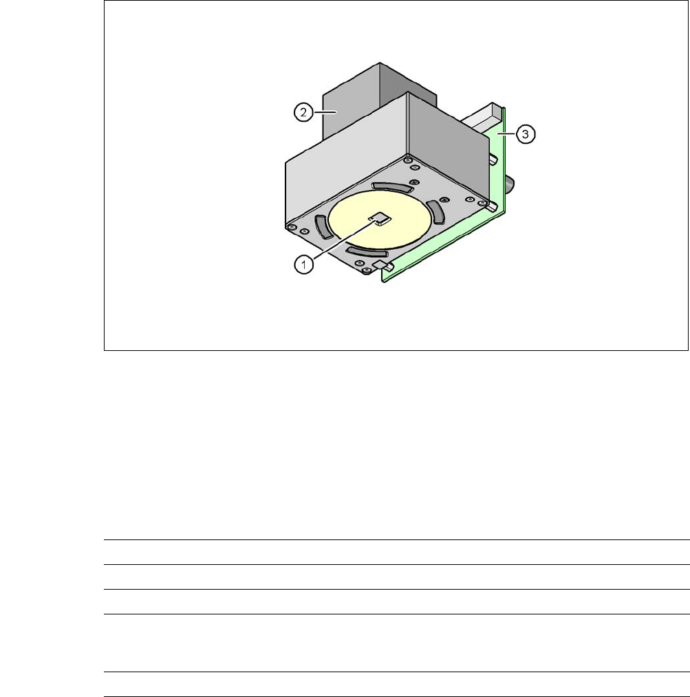
Fig. 7.5 - 1 PCB camera multicolor, type 24, digital
(1) PCB camera lens and illumination
(2) Camera amplifier
(3) Illumination control
7
7.5.2 Technical Data
7
Field of vision 5,7 mm x 5,7 mm
Distance of focus level 28 mm
Illumination method Front-illumination (5 levels, programable as required)
Fiducial size 0.3 mm to 2.5 mm edge length for a PCB feeder tolerance
of ± 1.0 mm
to 3.0 mm edge length for a PCB feeder tolerance of < 1.0 mm
Bad fiducial size 0.3 mm to 3.0 mm edge length

7 Station Enlargements User Manual SIPLACE CA
7.5 PCB Camera Multicolor, Type 24, Digital Edition 08/2011 EN
466
7.5.3 Illumination Types
The following types of illumination can be selected on the multicolor PCB camera:
– White illumination
This type of illumination is used for standard PCBs with tinned fiducials.
– Blue oblique illumination
In most cases, this can be used to greatly improve the contrast with bright fiducials on a light
base material, such as ceramic or CEM. Fiducials covered with solder resist can also be de-
tected better on a light background.
– Infrared illumination
This type of illumination is particularly useful for fiducials that are covered with solder resist
or for fiducials on flex materials. When using silver or platinum fiducials on a ceramic base,
this type of illumination could also achieve better recognition results. This should be checked
in advance by performing a test centering/placement run.
7.5.4 Fiducials and Inkspot Criteria
Fiducial and inkspot criteria are described in section 3.13.6.3 and 3.13.6.4, page 232.