00195941-03-UM SiplaceCA-EN.pdf - 第466页
7 Station Enlargements User Manual SIPLACE CA 7.5 PCB Camera Multicolor, Type 24, Digital Edition 08/2011 EN 466 7.5.3 Illumination T ypes The following types of illumination can be selected on the mult icolor PCB camera…
User Manual SIPLACE CA 7 Station Enlargements
Edition 08/2011 EN 7.5 PCB Camera Multicolor, Type 24, Digital
465
7.5 PCB Camera Multicolor, Type 24, Digital
7.5.1 Structure
[00119774-xx]PCB camera, X series, multicolor, type 24
7
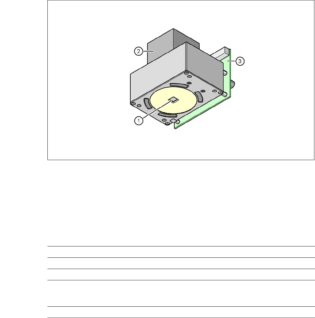
Fig. 7.5 - 1 PCB camera multicolor, type 24, digital
(1) PCB camera lens and illumination
(2) Camera amplifier
(3) Illumination control
7
7.5.2 Technical Data
7
Field of vision 5,7 mm x 5,7 mm
Distance of focus level 28 mm
Illumination method Front-illumination (5 levels, programable as required)
Fiducial size 0.3 mm to 2.5 mm edge length for a PCB feeder tolerance
of ± 1.0 mm
to 3.0 mm edge length for a PCB feeder tolerance of < 1.0 mm
Bad fiducial size 0.3 mm to 3.0 mm edge length

7 Station Enlargements User Manual SIPLACE CA
7.5 PCB Camera Multicolor, Type 24, Digital Edition 08/2011 EN
466
7.5.3 Illumination Types
The following types of illumination can be selected on the multicolor PCB camera:
– White illumination
This type of illumination is used for standard PCBs with tinned fiducials.
– Blue oblique illumination
In most cases, this can be used to greatly improve the contrast with bright fiducials on a light
base material, such as ceramic or CEM. Fiducials covered with solder resist can also be de-
tected better on a light background.
– Infrared illumination
This type of illumination is particularly useful for fiducials that are covered with solder resist
or for fiducials on flex materials. When using silver or platinum fiducials on a ceramic base,
this type of illumination could also achieve better recognition results. This should be checked
in advance by performing a test centering/placement run.
7.5.4 Fiducials and Inkspot Criteria
Fiducial and inkspot criteria are described in section 3.13.6.3 and 3.13.6.4, page 232.

User Manual SIPLACE CA 7 Station Enlargements
Edition 08/2011 EN 7.6 PCB Barcode Scanner
467
7.6 PCB Barcode Scanner
7.6.1 Overview
[ 7
The PCB barcode scanner is used to automatically record and decode barcodes on PCBs. The
PCB barcode scanner sends the read data via its serial interface to the transport controller and
then for further processing to the machine controller via the CAN bus.
Fig. 7.6 - 1 PCB barcode block diagram
7
[00176117-XX] Cognex DataMan 100X
[00176112-XX] Assembly kit for DataMan X/HS/HF series topside
(for reading barcodes on the topside of the PCB, one per
barcode scanner)
[00176113-XX] Assembly kit for DataMan X/HS/HF series underside
(for reading barcodes on the underside of the PCB, one
per barcode scanner)
[00176118-XX] Cognex I/A module (one per SIPLACE line)
[00176119-XX] Cognex USB cable DM 100 USB (one per SIPLACE line)
[00176120-XX] Wiring for interface I/A box (one per SIPLACE line)
Device number
1
Barcode
scanner
topside
Distribution
board
Transport
controller,
right
Barcode
scanner
under-
2
3
Barcode
scanner
topside
Distribution
board
Transport
controller,
left
Barcode
scanner
under-
4
Machine
controller
Station
computer
SIPLACE Pro
computer
LANCAN busV-24V-24