00195941-03-UM SiplaceCA-EN.pdf - 第474页
7 Station Enlargements User Manual SIPLACE CA 7.10 Magnetic Pin Suppor t Edition 08/2011 EN 474 7.10 Magnetic Pin Support [001 19680-xx]Magnetic pin support s HS/HF/X/CA/D series Wide boards tend to deflect du ring place…

User Manual SIPLACE CA 7 Station Enlargements
Edition 08/2011 EN 7.9 Long Board Option
473
7.9 Long Board Option
[00119672-xx]Stopper, long board, SIPLACE HF/X/CA/D3
The following board formats can be placed with CA series machines:
7
7
7
We can supply the Long board option as a retrofit kit for placing PCBs that are over 450 mm long.
If the Long board option is installed, then the following PCB formats can be processed:
7
The retrofit kit consists of the following modules:
– Mechanics, comp.: stopper, sensors, cable and assembly parts
– Optional CD for enabling the function on the SIPLACE Pro computer
– Retrofit instructions
NOTE 7
The Long board option must be ordered 2x for the dual conveyor.
For more information, refer to the "Retrofitting Guide for the Long Board Option"
[00193888-01].
Single conveyor (standard width) 50 mm x 50 mm to 450 mm x 460 mm
Single conveyor: Wide board 50 mm x 50 mm to 450 mm x 508 mm
Dual conveyor (standard width) 50 mm x 50 mm to 450 mm x 216 mm
Dual conveyor: Wide board 50 mm x 50 mm to 450 mm x 250 mm
Dual Conveyor in Single Conveyor Mode 50 mm x 50 mm to 450 mm x 416 mm
Dual conveyor in Single conveyor mode: Wide board 50 mm x 50 mm to 450 mm x 450 mm
Single conveyor: Long board (standard width) 50 mm x 80 mm to 610 mm x 460 mm
Single conveyor: Wide board, Long board 50 mm x 80 mm to 610 mm x 508 mm
Dual conveyor: Long board 50 mm x 80 mm to 610 mm x 216 mm
Dual conveyor: Wide board, Long board 50 mm x 80 mm to 610 mm x 250 mm
Dual conveyor in Single conveyor mode: Long board 50 mm x 80 mm to 610 mm x 416 mm
Dual conveyor in Single conveyor mode: Wide board,
Long board
50 mm x 80 mm to 610 mm x 450 mm
7 Station Enlargements User Manual SIPLACE CA
7.10 Magnetic Pin Support Edition 08/2011 EN
474
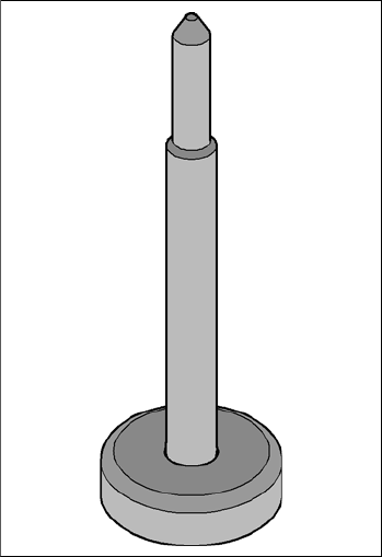
7.10 Magnetic Pin Support
[00119680-xx]Magnetic pin supports HS/HF/X/CA/D series
Wide boards tend to deflect during placement such that, under certain circumstances, the compo-
nents can no longer be placed with the desired accuracy. Highly curved PCBs also affect the
placement accuracy. This problem can be easily rectified by fitting magnetic pin supports on the
lifting table.
7
Fig. 7.10 - 1 Magnetic pin support
User Manual SIPLACE CA 7 Station Enlargements
Edition 08/2011 EN 7.11 Component Sensor for the C&P12 Head
475
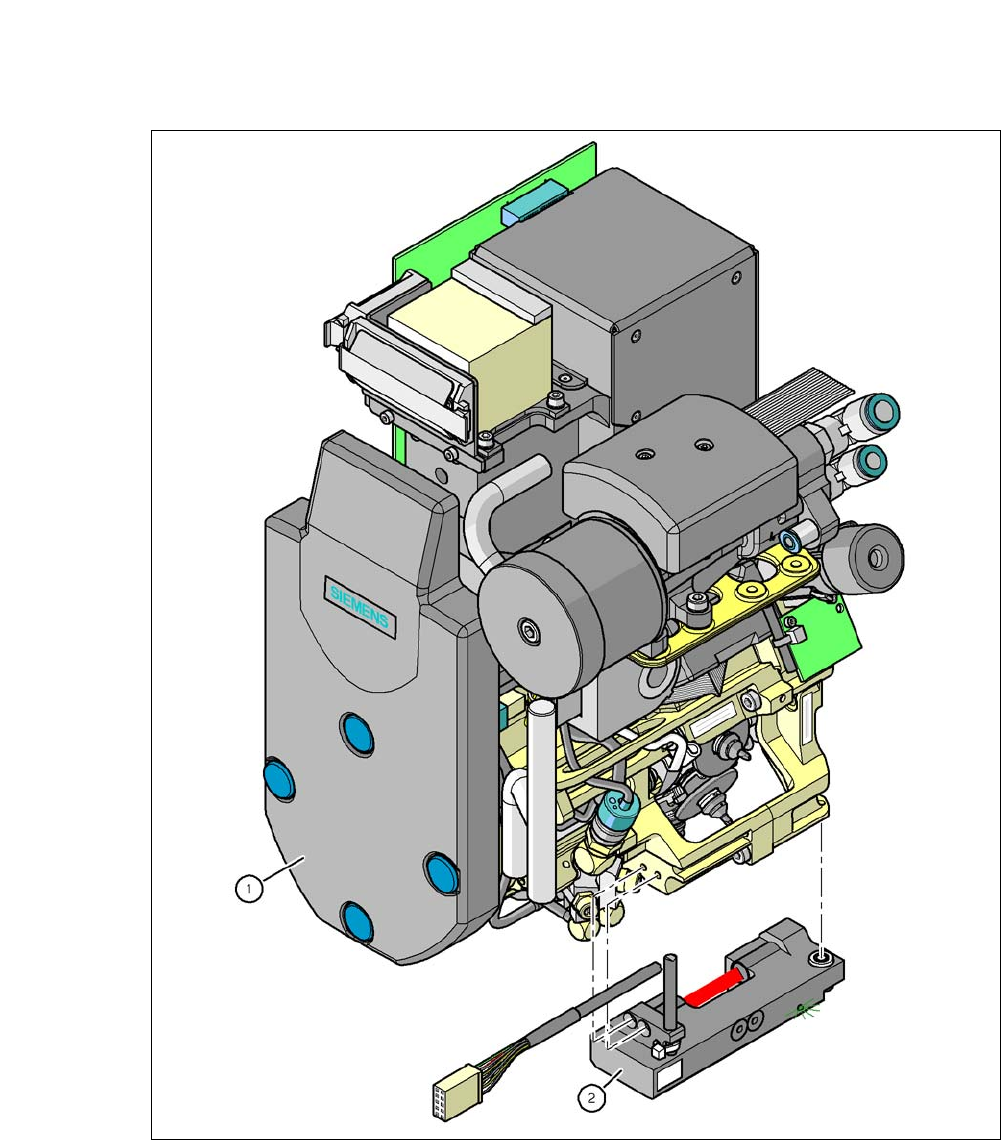
7.11 Component Sensor for the C&P12 Head
[00118021-xx]Component sensor for the 12 segment C&P head
7
Fig. 7.11 - 1 12 segment Collect&Place CA head with component sensor
(1) 12 Segment Collect&Place CA Head
(2) Component sensor