00195941-03-UM SiplaceCA-EN.pdf - 第479页
User Manual SIPLACE CA 7 Station Enlargements Edition 08/2011 EN 7.13 Coplanarity Laser Module 479 7.13 Coplanarity Laser Module [001 19719-xx] Coplanarity module SIPLACE X-/CA-/D- series 7.13.1 Functional Description Th…
7 Station Enlargements User Manual SIPLACE CA
7.12 High-Resolution CO Camera for the 12 Segment C&P Head, Type 29 Edition 08/2011 EN
478
7.12 High-Resolution CO Camera for the 12 Segment C&P Head, Type 29
[00119779] High resolution camera, C&P12, digital
7.12.1 Structure
7
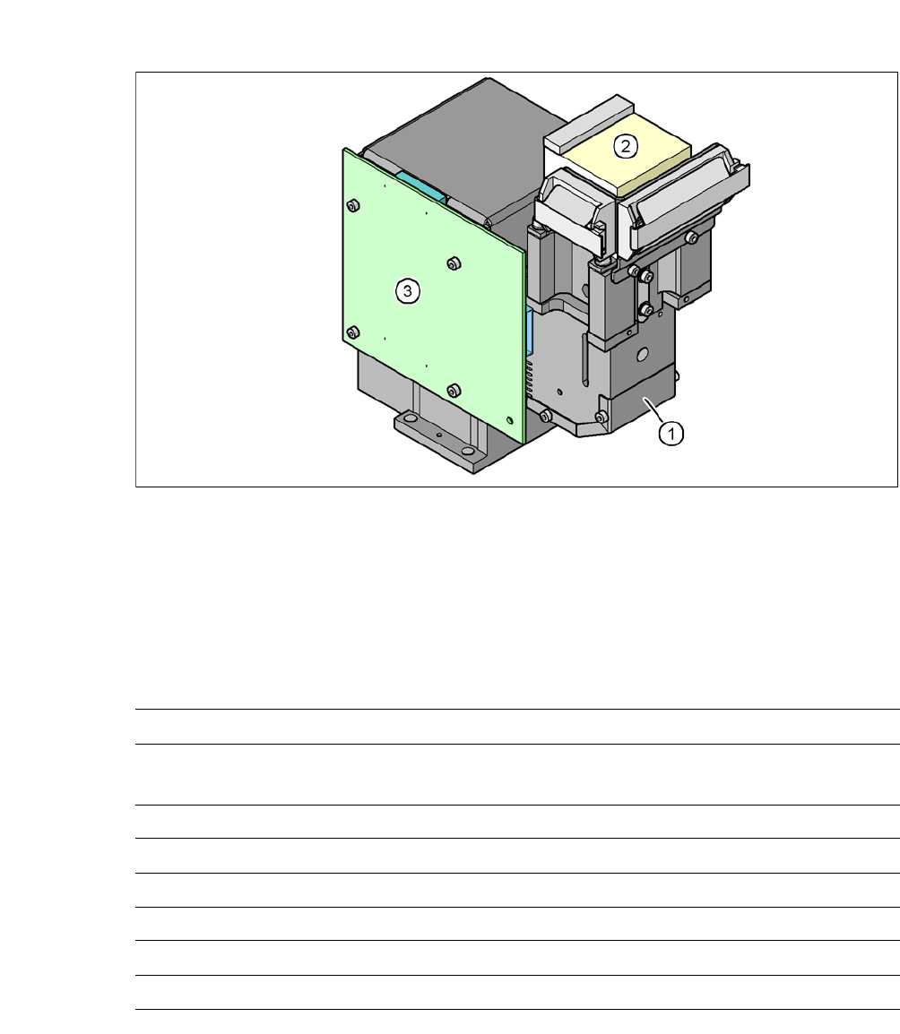
Fig. 7.12 - 1 C&P component camera, type 29, 27 x 27, digital
(1) Component camera lens and illumination
(2) Camera amplifier
(3) Illumination control
7.12.2 Technical Data
7
Component dimensions 0,3 mm x 0,3 mm to 18,7 mm x 18,7 mm
Range of components 0201
a
18,7 mm 18,7 mm to flip chip, bare die, PLCC44, BGA, µBGA,
TSOP, QFP, SO to SO32, DRAM
Min. lead pitch 0.3 mm
Min. lead width 0.15 mm
Min. ball pitch 0.25 mm
Min. ball diameter 0.14 mm
Field of vision 32 mm x 32 mm
Illumination method Front-illumination (5 levels, programable as required)
a) With 0201 package
User Manual SIPLACE CA 7 Station Enlargements
Edition 08/2011 EN 7.13 Coplanarity Laser Module
479
7.13 Coplanarity Laser Module
[00119719-xx] Coplanarity module SIPLACE X-/CA-/D-series
7.13.1 Functional Description
The coplanarity laser module is used to measure vertical bending of the leads. The lead length is
measured without contact using the laser triangulation principle.
7
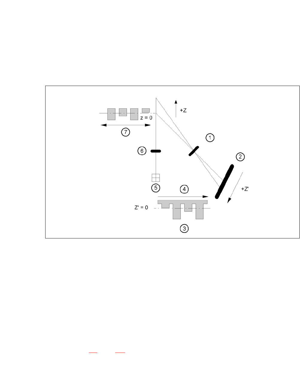
Fig. 7.13 - 1 Laser triangulation measurement principle
(1) Receiver lens
(2) Detector
(3) Measuring signal
(4) Time t
(5) Laser
(6) Transmitter lens
(7) Travel direction
7
The TwinHead picks up the component to be checked, enters it optically with the component cam-
era (see section 7.4
, page 463) and moves in succession all four sides over the fixed laser beam
of the coplanarity laser module. In this way, every lead is scanned from below by the laser beam.
The laser light scattered by the underside of the lead is recorded by a sensor, and is then used to
calculate the exact position of the lead with respect to the PCB.

7 Station Enlargements User Manual SIPLACE CA
7.13 Coplanarity Laser Module Edition 08/2011 EN
480
The position values thus calculated are compared against the limit value specified by the user. If
they exceed this value, the component is disposed of or returned.
The coplanarity laser module is used in combination with the optical component centering mode.
Components with bent or missing leads are detected and disposed of, if necessary.
7.13.2 Technical Data
Component spectrum: Usable for ’Gullwing’-component packages, pitch > 0,3 mm
and maximum component size 55 mm x 55 mm. Further
restrictions depend on the machine configuration.
Measuring principle: Measurement without contact via laser triangulation
Algorithm functions: JEDEC standard - calculation of contact level: all deviations
are calculated in relation to this level. If the component is
angled with respect to the vacuum nozzle, as can happen if
an adapter is used, then it will have no influence over the
choice between ‘good’ and ‘bad’.
Measuring range: 3 mm
Measuring range start (SMR) 24 mm
Reference distance
Measuring range center (MMR) 25.5 mm
Measuring range end (EMR) 27 mm
Linearity ± 1.5 µm
Resolution: 0.15 µm
Measuring rate 10 kHz
Wave length 670 nm, red
Max. output 1 mW
Laser Class 2
Permissible ambient light: 30,000 lx
Light spot diameter SMR 80 µm
MMR 35 µm
EMR 80 µm
Operating temperature: 0°C ... + 50°C
Storage temperature - 20°C ... + 70°C
Sensor protection class IP 65
Controller protection class IP 50
Supply voltage 24 VDC (± 15%, max. 500 mA)
Output, digital RS 422, 687.5 kBaud