00195941-03-UM SiplaceCA-EN.pdf - 第65页
User Manual SIPLACE CA 2 Operational Safety Edition 08/2011 EN 2.4 Laser Classification 65 2.4.2 Laser Class 1M Do not look directly at th is with optical instruments! 2 2.4.3 Laser Class 2 The following modules are assi…

2 Operational Safety User Manual SIPLACE CA
2.4 Laser Classification Edition 08/2011 EN
64
2.4 Laser Classification
2.4.1 Laser Class 1
2.4.1.1 Classification of Whole Machine
2
Note: 2
Modules in laser classes 1 and 1M are not identified.
2.4.1.2 Classification of Camera Systems
2
2
All installed camera systems and the whole machine when ready for oper-
ation are assigned to laser class 1.
The laser classes are determined according to DIN EN 60825-1:2001.
2
The following camera systems are assigned to laser class 1:
– PCB camera multicolor, Type 24, digital
– Component cameras for the SIPLACE TwinHead
Stationary P&P component camera, type 33, 55 x 45, digital
Stationary P&P component camera, type 25, 16 x 16, digital

User Manual SIPLACE CA 2 Operational Safety
Edition 08/2011 EN 2.4 Laser Classification
65
2.4.2 Laser Class 1M
Do not look directly at this with optical instruments!
2
2.4.3 Laser Class 2
The following modules are assigned to laser class 2:
– Laser light barrier, placement area 1 in the PCB conveyor
– Laser light barrier, placement area 2 in the PCB conveyor
– PCB barcode scanner
– Component sensor on 20 segment Collect&Place CA head
– Coplanarity laser module
(The whole machine is assigned to laser class 2, if the coplanarity laser module option is installed.)
2
2
The following camera systems are assigned to laser class 1M:
– C&P component camera, type 23, 6 x 6 on the 20-segment Collect&Place
CA head
– C&P component camera, type 41, 6 x 6 on the 20-segment Collect&Place
CA head
– C&P component camera, type 29, 27 x 27 on the 12-segment Collect&Place
CA head
– C&P component camera, type 29, 27 x 27 on the 6-segment Collect&Place
CA head
2
Laser radiation
Do not look into beam!
2 Operational Safety User Manual SIPLACE CA
2.5 Safety Instructions for Transportation Edition 08/2011 EN
66
2.5 Safety Instructions for Transportation
2.5.1 Transporting the Placement Machine
2
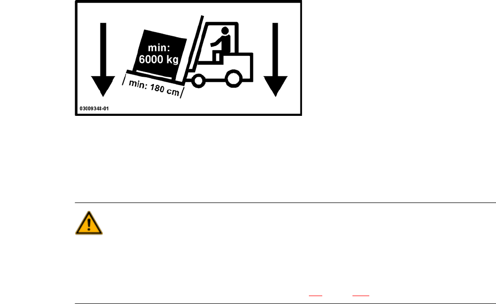
Use a fork-lift truck with the following specification to carry the machine:
Fork length: min. 1800 mm
Carrying power: min. 6000 kg
Clear width between forks: min. 350 mm 2
WARNING
RISK OF TIPPING 2
If the required specification cannot be applied to the fork-lift, there is a risk that the fork-lift will tip
over when carrying the placement machine.
Transportation of the machine is described in section 4.2, page 245.