00195941-03-UM SiplaceCA-EN.pdf - 第72页
2 Operational Safety User Manual SIPLACE CA 2.6 Safety Instructions for Operating the Placement Machine Edition 08/2011 EN 72 2.6.5 Safety Instructions for the T winHead Component Cameras during a Placement Head Change W…
User Manual SIPLACE CA 2 Operational Safety
Edition 08/2011 EN 2.6 Safety Instructions for Operating the Placement Machine
71
2.6.4 Safety Instructions for Manually Moving the Z Axis at the TwinHead
CAUTION
RISK OF CRUSHING AT THE TWINHEAD 2
NEVER move the Z axis down with your hand at the buffer of the retract unit. The strong spring
force of the cylinder poses a risk of injury to your fingers, when the bumper springs back. This
also applies to the inside of the TwinHead, when the piston rod return to its starting position.
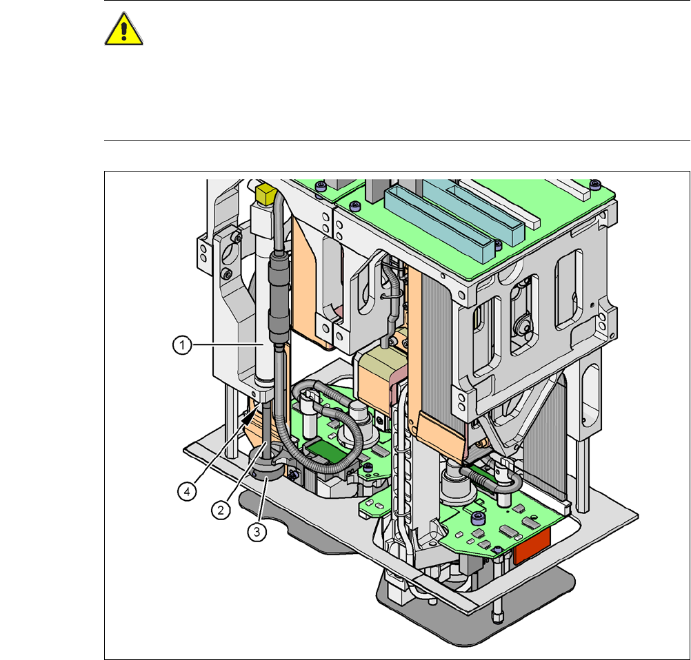
Fig. 2.6 - 3 Risk of crushing from the retract unit on the TwinHead
(1) Retract unit, compressed air cylinder
(2) Piston rod
(3) Bumper of the retract unit
(4) Crushing point for fingers
2 Operational Safety User Manual SIPLACE CA
2.6 Safety Instructions for Operating the Placement Machine Edition 08/2011 EN
72
2.6.5 Safety Instructions for the TwinHead Component Cameras during
a Placement Head Change
WARNING 2
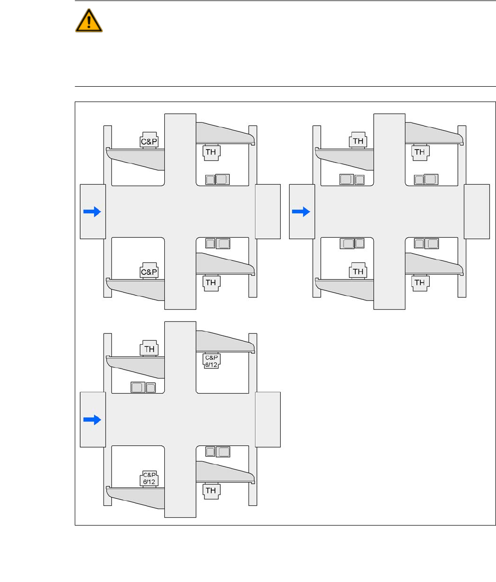
During a placement head change from TwinHead to Collect&Place CA head, the component
cameras (stationary P&P, type 33, 55 x 45, and type 25, 16 x 16) for the TwinHead must be dis-
mantled, otherwise the Collect&Place CA head will collide with the camera housings.
2
Fig. 2.6 - 4 Safety Instructions for the Vision Modules during a Placement Head Change
25 FC camera, type 25
33 IC camera, type 33
33 and 25
25 and 33
25 or 33 33 or 25
33 or 25
25 or 33
25 or 33
G3
G3
G4
G4
G1
G2
G2
G1
G4
G3
G2
G1
25 or 33
User Manual SIPLACE CA 2 Operational Safety
Edition 08/2011 EN 2.6 Safety Instructions for Operating the Placement Machine
73
2.6.6 Safety Instructions for Docking and Undocking the Component Trolley
WARNING
To prevent accidents (risk of crushing), the component trolley may only be docked in or out by
one person.
2
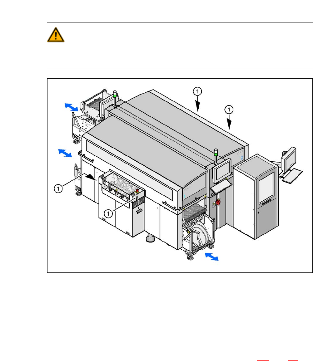
Fig. 2.6 - 5 Safety Instructions for docking and undocking the component trolley
2
(1) Buttons on the input and output sides
2
The safety concept for the component trolley change requires the operator to press a button (item
1) on the input or output side of the machine in order to dock the component trolley in or out. This
ensures that the operator is always standing to the side of the placement machine. In addition, the
component trolley can only be docked in if the protective covers are closed.
The docking and undocking of the component trolley is described in section 5.12
, page 368. Fol-
low the instructions exactly as described in this section.