00195941-03-UM SiplaceCA-EN.pdf - 第84页
2 Operational Safety User Manual SIPLACE CA 2.8 Safety Equipment Edition 08/2011 EN 84 Fig. 2.8 - 4 Position of switches and buttons - View of the PCB input side (1) EMERGENCY STOP bu tton on the input side (2) S tart bu…
User Manual SIPLACE CA 2 Operational Safety
Edition 08/2011 EN 2.8 Safety Equipment
83
2.8.2 Switches and Buttons on the Machine and SWS
2.8.2.1 Position of Switches and Buttons on the Machine and SWS
2
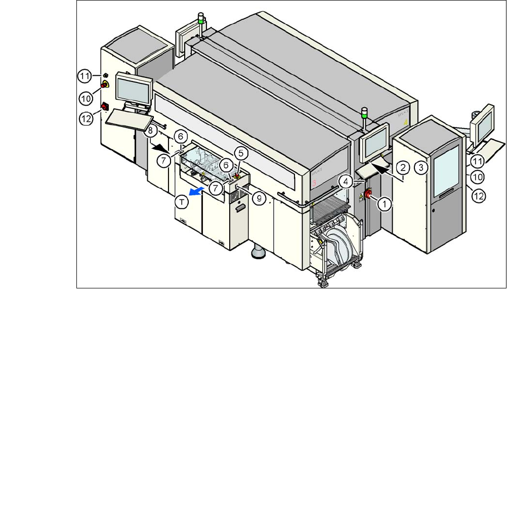
Fig. 2.8 - 3 Position of switches and buttons - View of the PCB output side
(1) Main switch on machine
(2) Stop button (black) on the operator panel on the power supply side
(3) Start button (white) on the operator panel on the power supply side
(4) Component counter on the operator panel on the power supply side
(5) EMERGENCY STOP button on the output side
(6) Start button (white) on the output side
(7) Stop button (black) on the output side
(8) Button (black) for docking the component trolley in or out, location 2
(9) Button (black) for docking the component trolley in or out, location 3
(10)EMERGENCY STOP button on the SWS
(11) Operating status indicator on the SWS
(12)Main switch at the SWS
(T) PCB transport direction
2
2 Operational Safety User Manual SIPLACE CA
2.8 Safety Equipment Edition 08/2011 EN
84
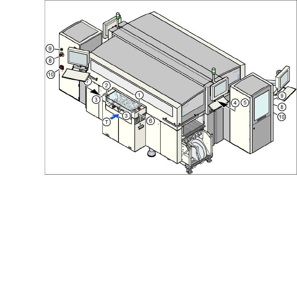
Fig. 2.8 - 4 Position of switches and buttons - View of the PCB input side
(1) EMERGENCY STOP button on the input side
(2) Start button (white) on the input side
(3) Stop button (black) on the input side
(4) Start button (white) on the operator panel on the compressed air unit side
(5) Stop button (black) on the operator panel on the compressed air unit side
(6) Button (black) for docking the component trolley in or out, location 1
(7) Button (black) for docking the component trolley in or out, location 4
(8) EMERGENCY STOP button on the SWS
(9) Operating status indicator on the SWS
(10)Main switch at the SWS
(T) PCB transport direction

User Manual SIPLACE CA 2 Operational Safety
Edition 08/2011 EN 2.8 Safety Equipment
85
2.8.2.2 Function of Switches and Buttons on the Machine
Main Switch in Position OFF (see item 1 in fig.
2.8 - 3) 2
The main power switch disconnects the three phases L1, L2, and L3 from the power supply.
WARNING
The following components still carry potentially lethal voltages even if the main power switch is
switched off:
– Cable connection terminals L1, L2, and L3 of the Q1 main power switch
– Z1 line filter
– Service socket X102
– F1 automatic circuit breaker for the service socket
– The color of all individual wires, which still carry potentially lethal voltages even if the main
power switch is switched off, is brown.
Death, serious injury or considerable damage may result if these automatic placement sys-
tems are handled incorrectly.
Always follow the applicable accident prevention and DIN regulations (particularly DIN EN 60
204, part 1) and the applicable regulations in your own country.
The safety door to the power supply must ONLY be opened by appropriately qualified and
trained personnel.
Main Switch in ON Position 2
After switching on the main power switch, the control computer and the machine controller will
start. All supply voltages, apart from the link voltages for the gantry axes (250 VDC) and the star
axes (145 VDC) are then available.
Black stop button (item 2 and 7 in fig. 2.8 - 3 and item 3 and 5 in fig. 2.8 - 4) 2
These buttons are used to stop the placement system.
White start button (item 3 and 6 in fig. 2.8 - 3 and item 2 and 4 in fig. 2.8 - 4) 2
After switching on the main power switch you will be prompted to press the Start button in order
to start the placement system for placement jobs. The same prompt appears if you open the pro-
tective covers or the press the EMERGENCY STOP button.
Component counter (item 4 in fig. 2.8 - 3) 2
This displays the number of inserted components.