00195941-03-UM SiplaceCA-EN.pdf - 第90页
2 Operational Safety User Manual SIPLACE CA 2.8 Safety Equipment Edition 08/2011 EN 90 2.8.3 Position of Protective Cont ac tor Combination and Service Socket 2 Fig. 2.8 - 6 Position of protective contactor combination a…
User Manual SIPLACE CA 2 Operational Safety
Edition 08/2011 EN 2.8 Safety Equipment
89
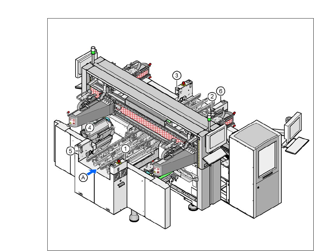
2.8.2.4 Position of Protective Switches at the Machine
2
Fig. 2.8 - 5 Position of protective switches at the machine
2
(1) Protective cover switch, location 1
(2) Protective cover switch, location 2
(3) Protective cover switch, location 3
(4) Protective cover switch, location 4
(5) Protective switch for the cover flap on the PCB conveyor input side
(6) Protective switch for the cover flap on the PCB conveyor output side
(A) PCB transport direction
2 Operational Safety User Manual SIPLACE CA
2.8 Safety Equipment Edition 08/2011 EN
90
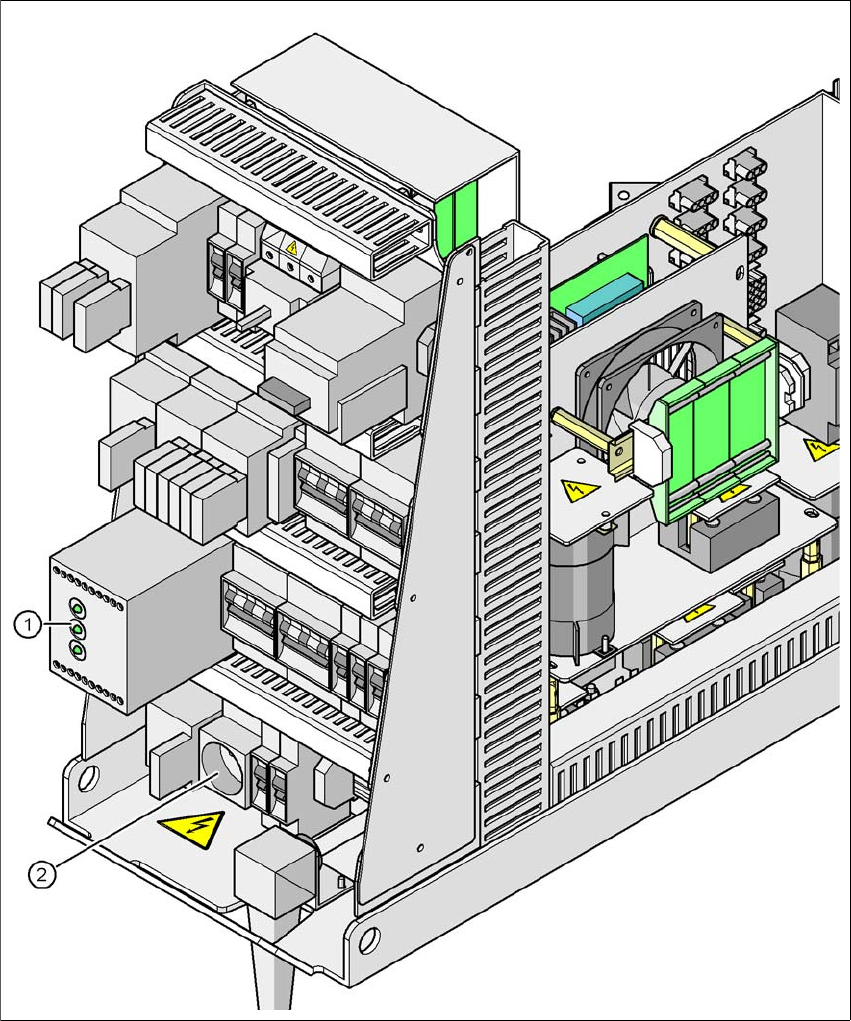
2.8.3 Position of Protective Contactor Combination and Service Socket
2
Fig. 2.8 - 6 Position of protective contactor combination and service socket
2
(1) Protective contactor combination
(2) Service socket

User Manual SIPLACE CA 2 Operational Safety
Edition 08/2011 EN 2.8 Safety Equipment
91
Protective contactor combination 3TK2806 2
The protective contactor combination is contained in the power supply unit. It is used to monitor
the EMERGENCY STOP circuits and safety equipment.
There are three conditions that must be fulfilled in order to activate the protective contactor com-
bination:
– The "software enable" signal must have been sent.
– The EMERGENCY STOP circuit must be closed.
– The Start button must have been pressed.
The front side of the protective contactor combination has three green LEDs for the status display
(see fig. 2.8 - 7
, page 92):
– The "Mains" LED indicates that voltage is present.
– The "Channel 1" and "Channel 2" LEDs light up if the Start button was pressed, the EMER-
GENCY STOP circuit is closed and the signaling circuit is not signaling a fault status.
Service socket (item 2 in fig. 2.8 - 6) 2
The service socket is contained in the power supply unit and is protected by the cover. It can only
be used if the placement system is connected to the main power supply via a 5-wire connection
(L1, L2, L3, N, and PE). If a 4-wire connection is used, e.g. without N, the socket cannot be used.
WARNING 2
Always follow the safety instructions concerning potentially lethal voltages - even when the
placement system is switched off. (See section 2.1.5 from page 35)
2.8.4 EMERGENCY STOP Circuits and Signaling Circuit on SIPLACE and SWS
The EMERGENCY STOP functionality of the SIPLACE has been enhanced by the EMERGENCY
OFF circuit of the SWS. For this reason the switching device 3TK2830-1CB30 (K6.1) has been
integrated into the power supply unit of the SIPLACE (see the plan "Extension of SIPLACE CA
EMERGENCY STOP" [00386139]).