00195941-03-UM SiplaceCA-EN.pdf - 第94页
2 Operational Safety User Manual SIPLACE CA 2.8 Safety Equipment Edition 08/2011 EN 94 2 Fig. 2.8 - 8 EMERGENCY STOP circuits S tart button pressed No No Ye s No No Ye s Ye s No Ye s 2 Active PCC a No Vo l t a g e Y -axi…

User Manual SIPLACE CA 2 Operational Safety
Edition 08/2011 EN 2.8 Safety Equipment
93
(3) Kanal 2 / Channel 2
(4) SWS EMERGENCY STOP switching device
extension K6.1 (3TK2830-1CB30)
2.8.4.2 Structure of the Signaling Circuit
The signaling contacts of the protective switches for protective covers, for cover flaps above the
PCB conveyor, for component trolleys or the SWSs as well as for EMERGENCY STOP buttons
are polled individually. All the signaling contacts are closed when the machine is on standby. If a
protective cover, for example, is raised, the associated signaling contact opens. This change of
state is signaled to the control computer via the CAN bus. The relevant error message will be dis-
played on the user interface of the station computer and the SWS.
2.8.4.3 Functional Description of the SIPLACE EMERGENCY STOP Circuits
The following conditions must be fulfilled in order to start and operate the placement machine:
– The existing component trolley must be docked and connected.
– The SWSs must be inserted and connected (
EMERGENCY STOP interface connector X1x).
– The SWS EMERGENCY STOP circuits (1 per SWS) must be closed.
– All protective covers must be closed.
– Both cover flaps over the PCB conveyor must be closed.
– The EMERGENCY STOP buttons on the placement machine (2) and on the SWS (1) must
be released.
– The cover flaps (option) over the feeder modules must be closed.
– The minimum operating pressure must have been reached.
– The "software enable" signal must be active. This ensures that the safety circuit is closed.
– The power supply must be sending 24 V to the Start buttons and the protective contactor
combination.
– If one of the start buttons is pressed, the protective contactor combination PCC 6 and the ex-
tension K6.1 are actuated and activate the following components:
– 250 VDC link voltage for the servo amplifiers for the gantry axes
– 145 VDC link voltage for the star axes
– The axis unit receives a "Servo enable" signal for the servo amplifiers.
– 34 VDC operating voltage is switched to the component trolleys.
– 24 V operating voltage are being sent to the used tape cutters.
– The PCB conveyor control receives the enable signal for the PCB clamping, the PCB
stopper and the lifting table control.
Thus the machine is ready to operate.
2 Operational Safety User Manual SIPLACE CA
2.8 Safety Equipment Edition 08/2011 EN
94
2
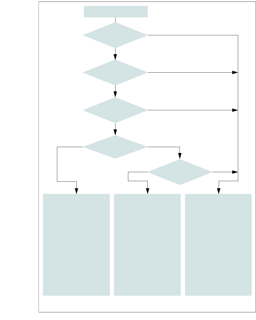
Fig. 2.8 - 8 EMERGENCY STOP circuits
Start button pressed
No
No
Yes
No
No
Yes
Yes
No
Yes
2
Active
PCC
a
No
Voltage
Y-axis 0 V-
X-axis 0 V-
Star axis 0 V-
DP axis 40 V-
Z-axis 40 V-
Active
PCB conveyor Yes
Lifting table No
PCB clamp No
Width adjustment No
Laser light barrier No
Empty tape cutter No
Component trolley feed device
2
Active
PCC
a
No
Voltage
Y-axis 0 V-
X-axis 0 V-
Star axis 0 V-
DP axis 40 V-
Z-axis 40 V-
Active
PCB conveyor No
Lifting table No
PCB clamp No
Width adjustment No
Laser light barrier No
Empty tape cutter No
Component trolley feed device
a) PCC protective contactor combination K6
Yes
Compressed
air min. 0.5 MPa
(5.0 bar)?
EMERGENCY STOP button
pressed?
Protective cover open ?
EMERGENCY STOP circuit
to component trolley and
SWS interrupted?
Barrier
activated on the user
interface?
2
Active
PCC
a
Yes
Voltage
Y-axis 250 V-
X-axis 250 V-
Star axis 145 V-
DP axis 40 V-
Z-axis 40 V-
Active
PCB conveyor Yes
Lifting table Yes
PCB clamp Yes
Width adjustment Yes
Laser light barrier Yes
Empty tape cutter Yes
Component trolley feed device

User Manual SIPLACE CA 2 Operational Safety
Edition 08/2011 EN 2.8 Safety Equipment
95
2.8.4.4 Structure and Control of the SWS EMERGENCY STOP Circuits
The following input and output signals control the EMERGENCY STOP circuit:
– Input 1 = 1 > EMERGENCY STOP button on the SWS is not pressed
– Input 16 = 1 > SWS EMERGENCY STOP circuit for switching device K3 is closed
– Input 1 = 0 / IN16 = 0 > EMERGENCY STOP activation of the SWS (internal)
– Input 1 = 1 / IN16 = 0 > EMERGENCY STOP activation of the SWS (external)
– Input 15= 1 > Contactors K1/K2 = on, 48 V DC control for the motor amplifiers = OK
– Output 1 = K4 (on/off 150 ms) > Resetting EMERGENCY STOP > Starting SWS
– Output 16 = 1 > K5 = On "Feeder Present" signal to the SIPLACE
2.8.4.5 Functional Description of the SWS EMERGENCY STOP Circuit
The EMERGENCY STOP switching device K3 is activated after switching on the SWS, if the fol-
lowing conditions are met:
– The SWS EMERGENCY STOP circuit is closed, i.e. the EMERGENCY STOP button on the
SWS is not pressed.
– The SIPLACE- EMERGENCY STOP circuit is closed, i.e. the protective cover is closed and
the start button is pressed.
– The initial condition of the inputs IN1 and IN16 is 1.
After that, the reset / start circuit is closed (by means of output 1 = K4 (on/off 150 ms) > resetting
the SWS EMERGENCY STOP).
– The contactors K1/K2 are being switched on (24 VDC coil).
– The link voltage of 48 V DC to the motor amplifiers DMC-19540(20) is supplied.
– The motor voltage is activated afterwards via the Enable signal from the motor controller.
– The ABORT signal (motor amplifier DMC-19540(20)) is deactivated via K2.
– A 24 V DC EMERGENCY STOP voltage is supplied.
– The compressed air main valve Y1/PRS for the die ejector lift is switched on.
– The operating status indicator (white) on the SWS is switched on.
The SWS is ready to operate.
Activating the EMERGENCY STOP
An EMERGENCY STOP can be triggered by:
– Pressing the EMERGENCY STOP button on the SWS.
– Pressing the EMERGENCY STOP button on the placement machine.
– Opening one of the protective covers of the placement machine.