88242361-04-01 Vol 1 DEK TQ TECHNICAL REFERENCE (1).pdfPDFA.pdf - 第136页
8 SQUEEGEE MODULE 8.4 CALIBRATIONS 136 TECHNICAL REFERENCE MANUAL DEK TQ 04/2021 22. Use the left and right jog buttons to move the squeegee up or down until the calibration jig dis- plays the same value (± 0.1Kg) as tha…
8 SQUEEGEE MODULE
8.4 CALIBRATIONS
TECHNICAL REFERENCE MANUAL DEK TQ 04/2021 135
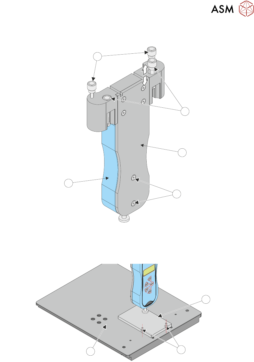
13. Ensure that the force gauge (4) is secured to the test jig mounting plate (2) using two securing
screws (3).
4
2
1
3
5
14. Raise the retractable front squeegee mount nuts (1).
15. Fit the calibration jig to the front squeegee mounting foot.
16. Fit the squeegee pressure plate (1) to the tooling table (3) ensuring that both locating dowels
(2) are inserted into the holes at the front of the tooling table.
1
2
3
17. Switch the force meter ON and check the reading is 0kg.
18. Close the front cover.
19. Press the System button.
20. Select Confirm.
The squeegee steps down until the pressure value stored on the machine is reached. The
screen displays the first Load Cell Calibration Point value(1kg).
21. Switch on the internal light.
8 SQUEEGEE MODULE
8.4 CALIBRATIONS
136 TECHNICAL REFERENCE MANUAL DEK TQ 04/2021
22. Use the left and right jog buttons to move the squeegee up or down until the calibration jig dis-
plays the same value (± 0.1Kg) as that shown on the screen. Achieving the exact value may
not be possible.
NOTE
For improved accuracy, all calibrations should be made by adding pressure. If the gauge
value exceeds the requested calibration value, raise the jig and re-apply pressure starting at a
value below the requested value.
23. Select Accept and Continue.
24. Repeat Steps 22 and 23 for the next four Load Cell Calibration Points (4kg, 8kg, 11kg and
21kg).
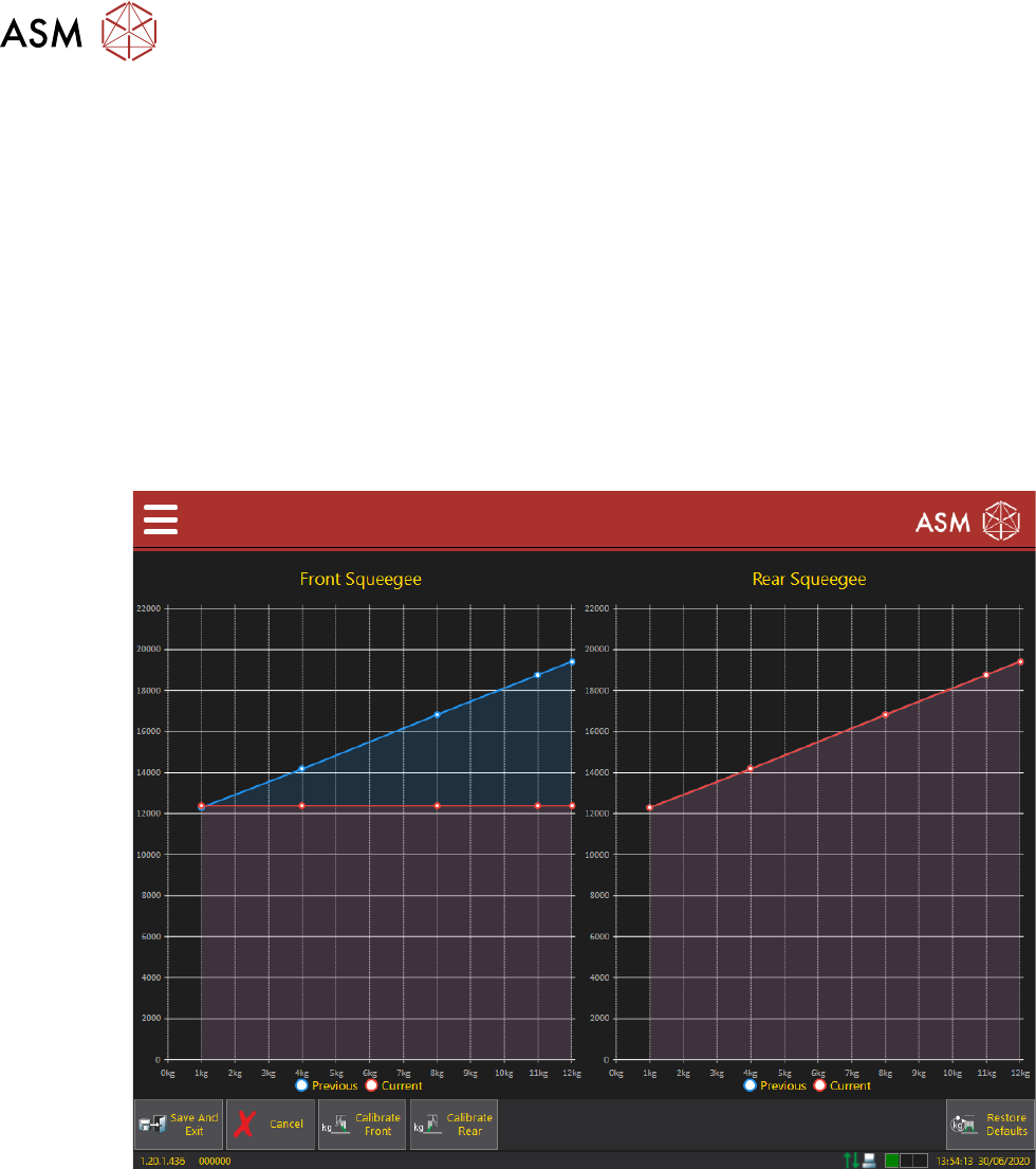
Once the last calibration point is complete, the new calibration data points are added to the
squeegee load cell pressure calibration chart, allowing a visual comparison with previously
stored values. Selecting individual data points displays an overlay listing values for that points
previous and current calibrations.
25. Select Calibrate Rear.
26. Open the front cover.
27. Remove the calibration jig from the front squeegee position.
28. Retract the front squeegee mounting nuts (1).
29. Using the rear mounting nuts (5), fit the calibration jig to the rear squeegee mounting foot.
30. Close the front cover.
31. Press the System button.
32. Select Confirm.
The squeegee steps down until the pressure value stored on the machine is reached. The
screen displays the first Load Cell Calibration Point value (1kg).
8 SQUEEGEE MODULE
8.4 CALIBRATIONS
TECHNICAL REFERENCE MANUAL DEK TQ 04/2021 137
33. Carry out calibration as detailed in Steps 21 to 24.
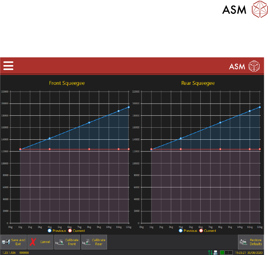
Once the rear squeegee load cell calibration is complete, both the Front and Rear Squeegee
Load Cell Calibration screens are displayed.
34. Select Save And Exit.
35. Open the front cover.
36. Remove the calibration jig from the rear squeegee mount.
37. Remove the pressure plate from the tooling table.
38. Refit the tooling, stencil and squeegees, if required.
39. Close the front cover.
40. Press the System button.
41. Select Confirm.
42. Select Confirm.
43. Select Exit.