88242361-04-01 Vol 1 DEK TQ TECHNICAL REFERENCE (1).pdfPDFA.pdf - 第142页
9 PASTE DISPENSER SYSTEM 9.1 OVERVIEW 142 TECHNICAL REFERENCE MANUAL DEK TQ 04/2021 9.1.1.2 Paste Jar Paste is dispensed by applying pneumatic pressure to the base of the paste jar, driving the jar downwards over the pas…
9 PASTE DISPENSER SYSTEM
9.1 OVERVIEW
TECHNICAL REFERENCE MANUAL DEK TQ 04/2021 141
5
4
3
2
1
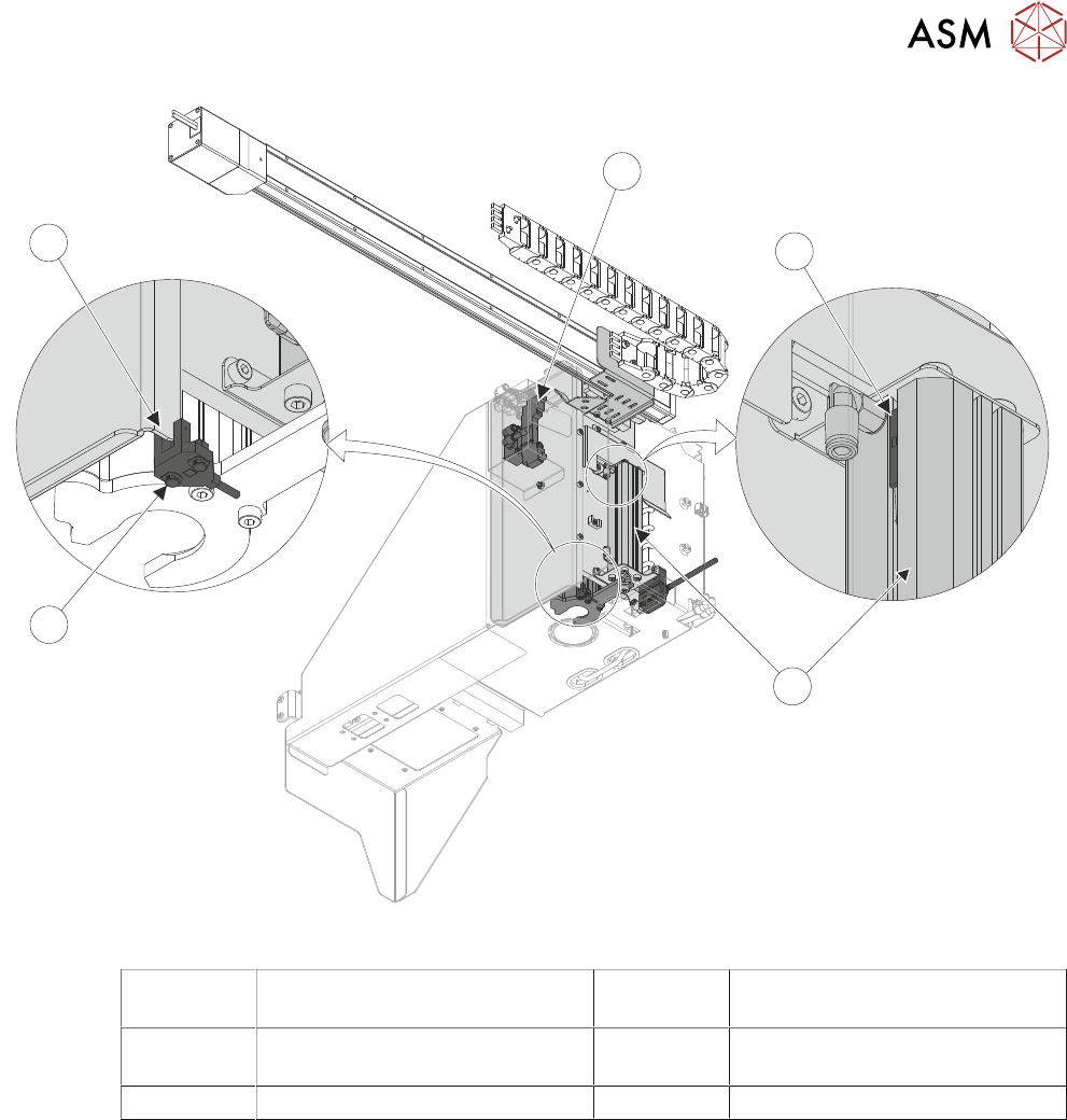
Paste Dispenser System - View On Rear
1 Paste Dispenser Pneumatic
Solenoid
4 Paste Dispenser Home Sensor
2 Paste Dispenser Z Axis Reed
Switch
5 Paste Dispenser Home Sensor
Vane
3 Paste Dispenser Z Axis Cylinder
9.1.1 Paste Dispenser
The paste dispenser is driven in the X direction by a stepper motor. This enables accurate position-
ing of paste onto the stencil in the X direction. The paste dispenser is mounted vertically and is
pneumatically driven to the paste dispensing height in the Z direction only when it is over the sten-
cil. There are two inter-changeable dispenser types:
●
Paste Cartridge
●
Paste Jar
9.1.1.1 Paste Cartridge
The paste dispenser is designed to accommodate cartridges up to 1kg in size. The paste is dis-
pensed by applying pneumatic pressure to the paste cartridge.
The paste dispenser is supplied with an extra pneumatic cartridge cap and paste cartridge anti-drip
nozzles to help with a fast changeover when the cartridge needs replenishment.

9 PASTE DISPENSER SYSTEM
9.1 OVERVIEW
142 TECHNICAL REFERENCE MANUAL DEK TQ 04/2021
9.1.1.2 Paste Jar
Paste is dispensed by applying pneumatic pressure to the base of the paste jar, driving the jar
downwards over the paste jar piston assembly, forcing the paste out of the jar, into the paste trans-
fer tube and through the anti-drip nozzle on to the stencil.
A paste jar release switch, activated through the HMI software, applies pneumatic pressure to the
opposite end of the paste jar pneumatic cylinder, removing pressure from the base of the paste jar.
Once fully released, the user can easily remove the piston and nozzle to replace the paste jar.
9.1.2 Paste Dispenser Regulator
The pneumatic pressure used to dispense the paste is variable depending on the viscosity of the
print medium being used and the flow of the print medium required. The regulator can be adjusted
to increase or decrease the pneumatic pressure applied to either the cartridge or jar dispenser.
9.1.3 Sensors
9.1.3.1 Home Position Sensor
The paste dispenser mechanism is fitted with a through beam optical sensor which detects a vane
fitted to the dispenser carriage. This is utilised as the home position sensor.
9.1.3.2 Cartridge Low Level Sensor
The cartridge paste dispenser uses a proximity sensor to detect the level of paste.
The paste low level sensor is designed to alert the operator when the paste level reaches low level.
The paste cartridge is checked when in the home position.
9.1.3.3 Paste Jar Low Level Sensor
The paste jar dispenser is fitted with a reed switch on the pneumatic actuator. Once the piston in-
side the actuator reaches a certain position, this activates the reed switch providing a paste low
level indication.
9 PASTE DISPENSER SYSTEM
9.2 ELECTRICAL SCHEMATIC
TECHNICAL REFERENCE MANUAL DEK TQ 04/2021 143
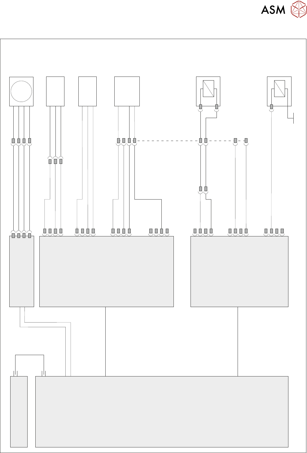
9.2 ELECTRICAL SCHEMATIC
Machine Controller
Controller Power Module
(CPM)
Fibre
Optic
Links
Ribbon Cables
SIO Link Cable
SIO Link Cable
M
Paste
Dispense
Drive
MTR20
Paste Low
4SE18
Dispense
Drop Home
4SE20
Extended Power Module
EPM2-2
J2
EPM2PL10
5PL34
Paste
Dispense
Pressure
5SOL10
Paste
Dispense
Drop
5SOL9
ESIO-5
IO13
IO11
IO12
ESIO-4
IO15
IO20
IO6
IO21
4PL25
4PL6
Home
4SE21
Sensor
Sensor
Sensor
5SK19
3SK2
0V
Paste Dispenser - Cartridge