88242361-04-01 Vol 1 DEK TQ TECHNICAL REFERENCE (1).pdfPDFA.pdf - 第170页
10 STENCIL ALIGNMENT MODULE 10.1 OVERVIEW 170 TECHNICAL REFERENCE MANUAL DEK TQ 04/2021 10.1.4.1 Stencil Clamp Adapter 1 2 1 Stencil Clamp Adapter 2 Pneumatic Stencil Clamp The stencil clamp adapter replaces the pneumati…
10 STENCIL ALIGNMENT MODULE
10.1 OVERVIEW
TECHNICAL REFERENCE MANUAL DEK TQ 04/2021 169
A stencil is manually loaded into the machine by the operator and the stencil loading mechanism
accurately positions the stencil in the chase. It is incorporated into the print carriage, using a re-
tractable paddle to manoeuvre the stencil backwards and forwards to its correct position.
When Load Stencil is selected, the print carriage drives forward until the rear edge of the stencil is
located by the stencil presence sensor. The print carriage is then driven forwards until it clears the
inner face of the stencil frame. The stencil paddle is lowered, and the print carriage is reversed,
driving the stencil to the rear of the chase. Once in position, the paddle retracts and the print car-
riage drives back by the set ‘hop over distance’, passing over the stencil frame again, the paddle is
lowered and pushes the stencil forwards into the correct position. The paddle is retracted and the
stencil clamps are activated.
The stencil presence sensor, located on the inside of the print carriage, is a photoelectric diffuse
sensor, and has dual functionality. It is used to both confirm the presence of a stencil in the chase,
and to locate the edge of the stencil during the loading procedure.
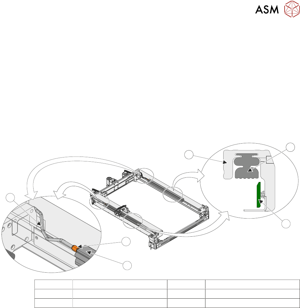
10.1.4 Stencil Clamps
3
1
4
2
2
5
1 Adjustable Stencil Holder 4 Pneumatic Quick Release Fitting
2 Pneumatic Stencil Clamp 5 Pneumatic Tube
3 Stencil Guide Strip
Once the stencil is in position, it is clamped using a pair of pneumatically operated stencil clamps.
The clamps are hollow rubber bladders and when pneumatic pressure is applied they expand
providing a downward force onto the stencil frame.
10 STENCIL ALIGNMENT MODULE
10.1 OVERVIEW
170 TECHNICAL REFERENCE MANUAL DEK TQ 04/2021
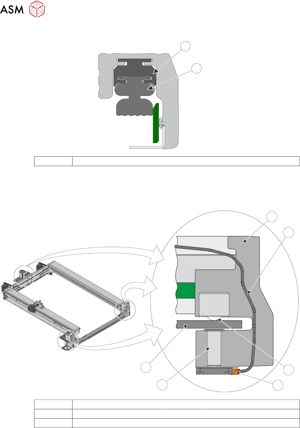
10.1.4.1 Stencil Clamp Adapter
1
2
1 Stencil Clamp Adapter 2 Pneumatic Stencil Clamp
The stencil clamp adapter replaces the pneumatic stencil clamp in the chase housing and the
clamp fits to the adapter. This lowers the clamp by 15mm
allowing for stencil frames of 10 to 24mm
height to be used and clamped securely.
10.1.5 Chase Clamps
1
6
5
2
4
3
1 Chase Clamp Housing 4 Pneumatic Valve
2 Air Supply Tube 5 Clamp Lift Piston
3 Roller Ball 6 Roller Plate
The chase runs on three roller balls and is positioned using the three alignment actuators. Once in
the correct position, a pneumatic valve at the base of the chase clamp housing activates, forcing a
piston to rise and clamp the chase against the roller plate which is attached to the machine frame.
10 STENCIL ALIGNMENT MODULE
10.1 OVERVIEW
TECHNICAL REFERENCE MANUAL DEK TQ 04/2021 171
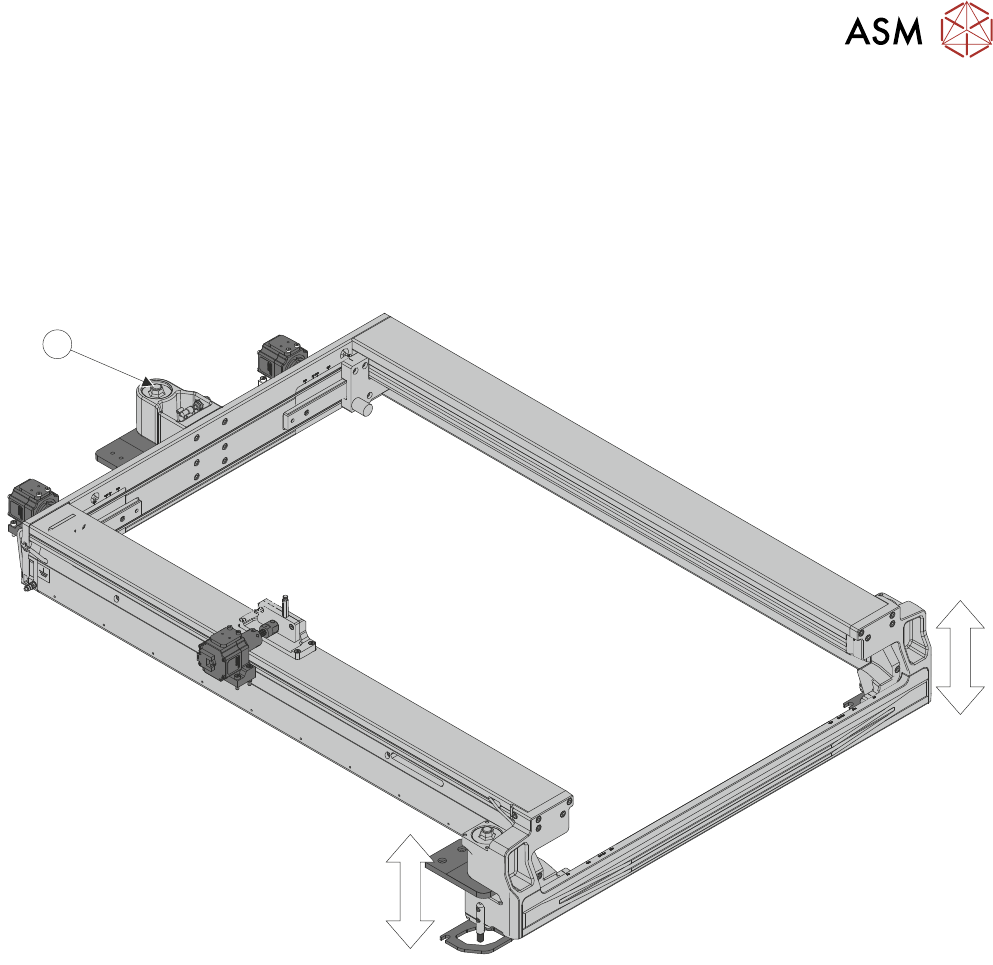
10.1.6 Coplanarity
When the product board is lifted up to the stencil ready for printing, the board and stencil must be
parallel to produce a good quality print. Coplanarity ensures that the chase (which secures the
stencil) is parallel to the centre section of the transport conveyors (which secures the board).
The chase is secured at a set height at the rear of the machine pivoting on a single point (1). The
front of the chase can be adjusted on the right and left side allowing the chase to be levelled in the
X and Y planes. Moving both sides equally levels the chase in Y, moving one side only, levels the
chase in the X.
1