88242361-04-01 Vol 1 DEK TQ TECHNICAL REFERENCE (1).pdfPDFA.pdf - 第172页
10 STENCIL ALIGNMENT MODULE 10.1 OVERVIEW 172 TECHNICAL REFERENCE MANUAL DEK TQ 04/2021 There are two methods to coplane the chase: A B ● A - Manual ● B - Auto (Optional) Manual coplanarity is fitted as standard on the m…
10 STENCIL ALIGNMENT MODULE
10.1 OVERVIEW
TECHNICAL REFERENCE MANUAL DEK TQ 04/2021 171
10.1.6 Coplanarity
When the product board is lifted up to the stencil ready for printing, the board and stencil must be
parallel to produce a good quality print. Coplanarity ensures that the chase (which secures the
stencil) is parallel to the centre section of the transport conveyors (which secures the board).
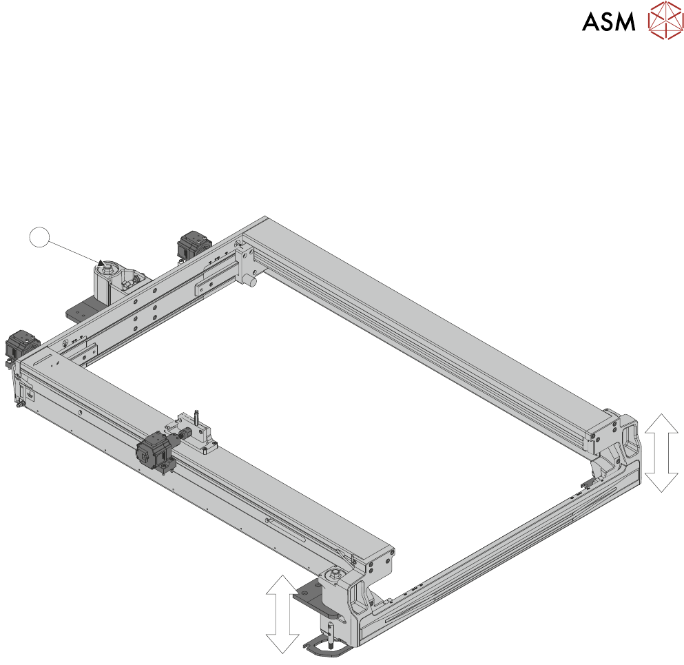
The chase is secured at a set height at the rear of the machine pivoting on a single point (1). The
front of the chase can be adjusted on the right and left side allowing the chase to be levelled in the
X and Y planes. Moving both sides equally levels the chase in Y, moving one side only, levels the
chase in the X.
1
10 STENCIL ALIGNMENT MODULE
10.1 OVERVIEW
172 TECHNICAL REFERENCE MANUAL DEK TQ 04/2021
There are two methods to coplane the chase:
A B
●
A - Manual
●
B - Auto (Optional)
Manual coplanarity is fitted as standard on the machine, where accurate measurements are taken
by an engineer between the chase and the top of the conveyors. The chase is adjusted in the X
and Y by the engineer to achieve parallelism.
NOTE
Manual coplanarity is achievedby using a calibration kit available from your local CSG office. The
kit comes with full instructionson the procedure.
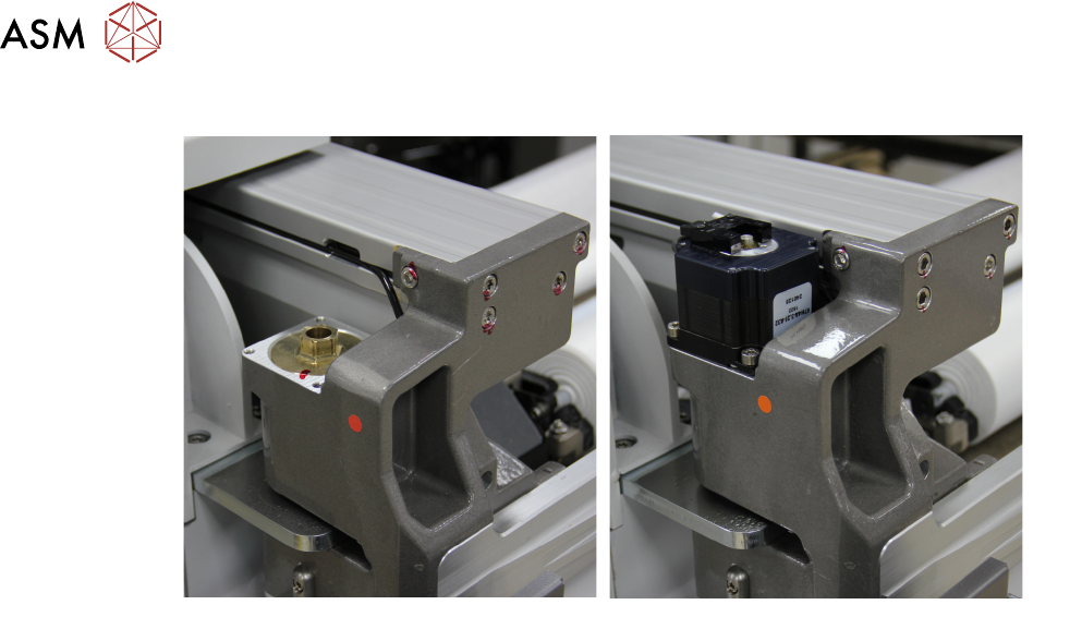
Auto coplanarity is an option on the machine, where accurate measurements are taken (by two
lasers) between the stencil and the top of the transport conveyors. The chase is automatically ad-
justed in the X and Y by two stepper motors to achieve parallelism.
10 STENCIL ALIGNMENT MODULE
10.1 OVERVIEW
TECHNICAL REFERENCE MANUAL DEK TQ 04/2021 173
10.1.6.1 Auto Coplanarity
2
1
4
7
6
5
3
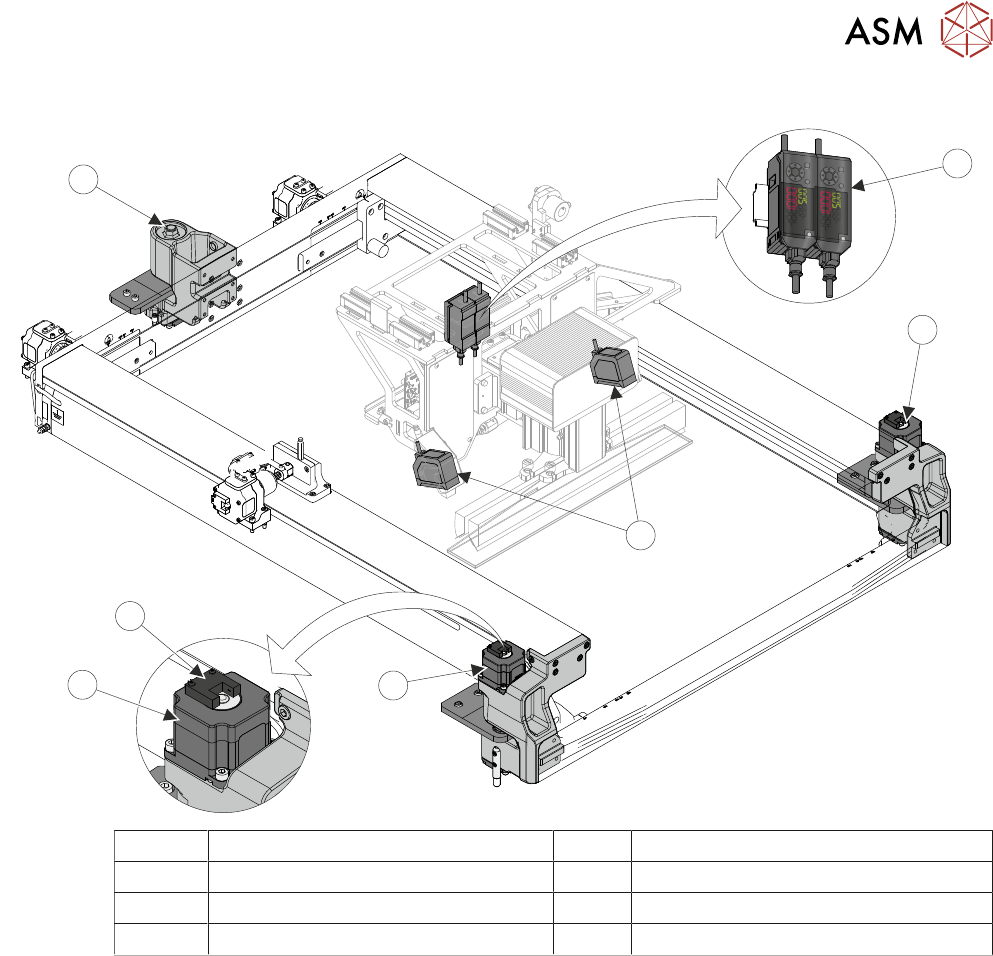
1 Laser Amplifiers 5 Stepper Motor
2 Right Hand Adjustment Motor 6 Home Sensor
3 Coplanarity Lasers 7 Rear Chase Pivot Point
4 Left Hand Adjustment Motor
Two laser sensors mounted on the print carriage are used to take accurate measurements allowing
the software to accurately parallel the stencil to the transport conveyors. With the stencil removed,
the laser sensors measure the distance to the top of the rear centre section of the conveyors. The
print carriage moves forward and measurements are taken to the top of the front centre section.
With the stencil fitted, the laser sensors measure the same four positions. The software uses this
information to calculate the error and level the stencil to the top of the conveyors and drives the co-
planarity motors to achieve this.