88242361-04-01 Vol 1 DEK TQ TECHNICAL REFERENCE (1).pdfPDFA.pdf - 第177页
10 STENCIL ALIGNMENT MODULE 10.2 ELECTRICAL SCHEMATIC TECHNICAL REFERENCE MANUAL DEK TQ 04/2021 177 Machine Controller Controller Power Module (C P M) Fibre Optic Links Ribbon Cables S IO Link Cable M M Coplanarity Left …
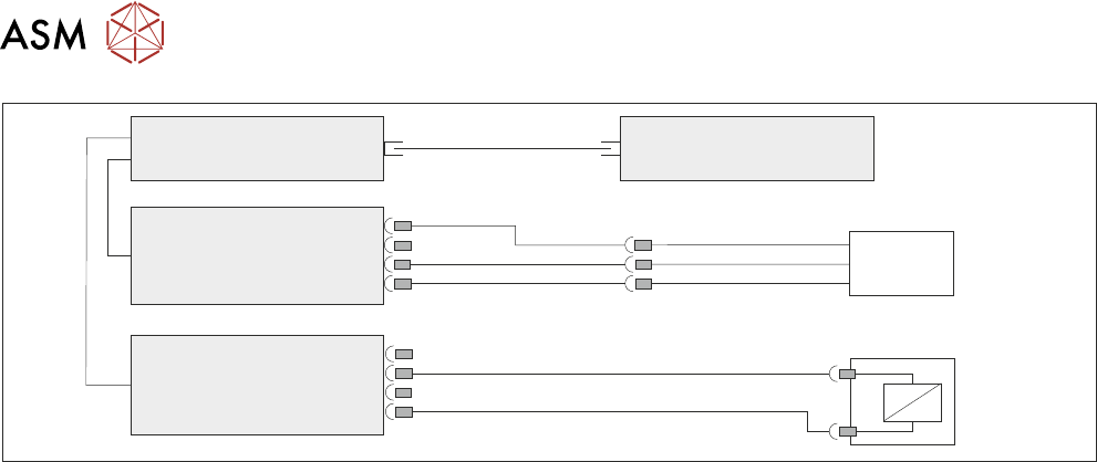
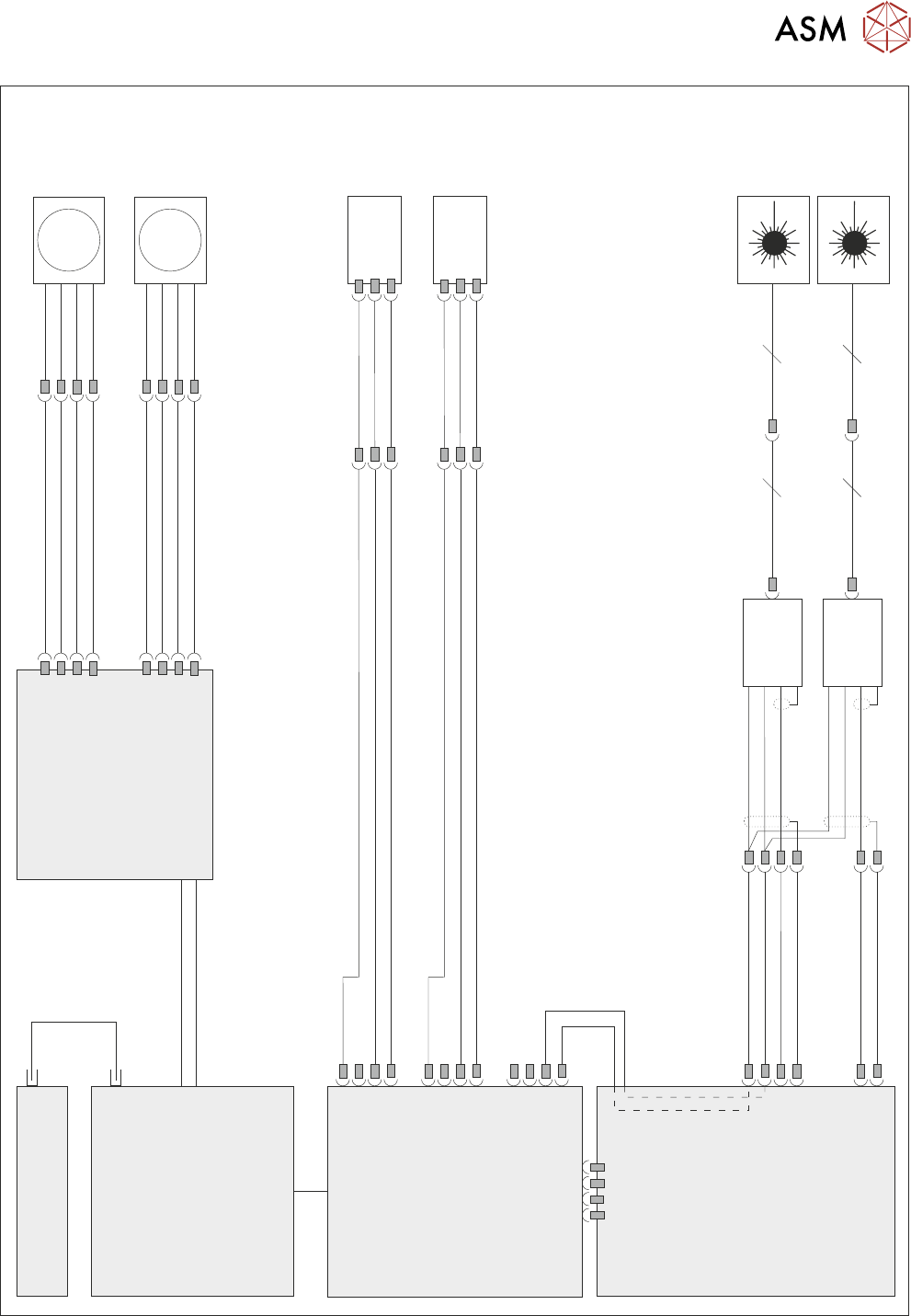
10 STENCIL ALIGNMENT MODULE
10.2 ELECTRICAL SCHEMATIC
176 TECHNICAL REFERENCE MANUAL DEK TQ 04/2021
Machine Controller
Controller Power Module
(CPM)
Fibre Optic Links
SIO
Link
Cables
ESIO-4
ESIO-5
IO5
4PL13
Stencil Load
Paddle Up
4SE12
Sensor
5SOL4
Stencil Load
Cylinder
5SOL4
IO1
Stencil Load
10 STENCIL ALIGNMENT MODULE
10.2 ELECTRICAL SCHEMATIC
TECHNICAL REFERENCE MANUAL DEK TQ 04/2021 177
Machine Controller
Controller Power Module
(CPM)
Fibre
Optic
Links
Ribbon Cables
SIO Link Cable
M
M
Coplanarity
Left
MTR22
Coplanarity
Right
MTR23
Extended Power Module
EPM1-1
J6
J7
MTR22
MTR23
6SE2A
ADC/DAC
Board 6
ESIO
Upper Frame 4
6PL3
6SE1A
6PL6
Amplifier
Amplifier
Coplanarity
Laser Left
6SE1
Coplanarity
Laser Right
6SE2
12 12
12 12
Coplanarity
Right Home
3SE6
IO1
IO2
IO16
6PL7
6PL8
Coplanarity
Left Home
3SE5
Sensor
Sensor
Auto Coplanarity
10 STENCIL ALIGNMENT MODULE
10.3 ADJUSTMENTS AND SETTINGS
178 TECHNICAL REFERENCE MANUAL DEK TQ 04/2021
10.3 ADJUSTMENTS AND SETTINGS
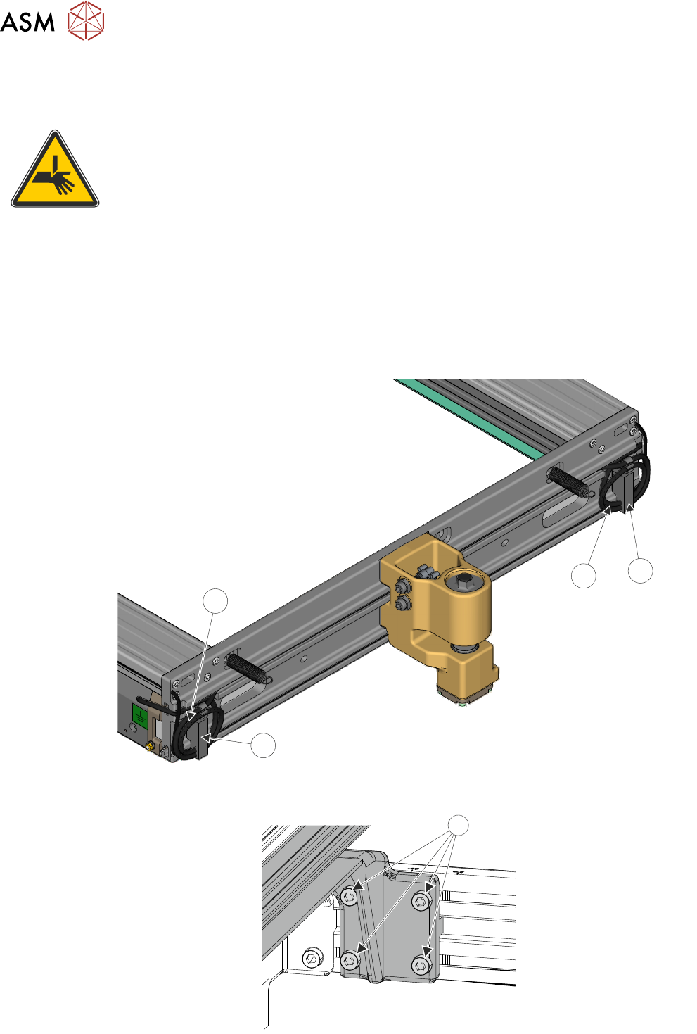
10.3.1 Stencil Width Adjustment
WARNING
BOARD CLAMPS. EXTREME CARE MUST BE EXERCISED WHEN WORKING IN
THE TOOLING AREA OF THE MACHINE TO AVOID INJURY. THE FOILS ON THE
FRONT AND REAR BOARD CLAMPS ARE VERY SHARP.
The chase holders are adjustable to suit various widths of stencil. Their positions are adjusted
manually, using the following method:
1. Shut down the software.
2. Switch the mains isolator to OFF.
3. Open the front cover.
4. Remove the rear upper panel.
5. Release the surplus pneumatic tubing (2) from the clips (1) on the left and right hand sides.
1
1
2
2
6. On the right hand side of the chase, using a 4mm Allen key, loosen the four securing screws
(1) that secure the adjustable stencil holder at the front.
1