88242361-04-01 Vol 1 DEK TQ TECHNICAL REFERENCE (1).pdfPDFA.pdf - 第19页
2 SAFETY FEATURES 2.3 SAFETY CIRCUIT TECHNICAL REFERENCE MANUAL DEK TQ 04/2021 19 2.3.3 Single Cover Machine The single cover allows access to the print and tooling area and the paste dispenser, if fitted. The cover has …
2 SAFETY FEATURES
2.3 SAFETY CIRCUIT
18 TECHNICAL REFERENCE MANUAL DEK TQ 04/2021
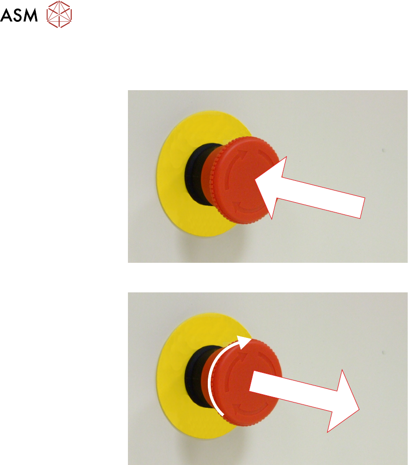
2.3.1 Emergency Stop (E Stop)
The machine is fitted with an E Stop which suspends all machine operations. The switch is within
easy reach of the operator and once pressed, the latching switch requires resetting.
To reset the E Stop, turn the button clockwise until it unlatches and extends outward.
Press the System button to reinitialise the machine.
2.3.2 Opening Cover
NOTE
The safety features designed into the printer are for the protection of all operators and maintenance
personnel. ASM strongly recommend safety devices are never overridden.
There are two variants of opening covers:
Dual Covers machine - Front Cover and Paste Dispenser Cover
Single Covers Machine - Front Cover
The cover(s) are fitted with safety switches to protect personnel from internal moving parts. The
cover(s) are secured by electromagnetic locks to prevent the cover from opening when not permit-
ted.
The front cover electromagnets are de-energised when:
●
Open Cover is selected on the monitor
●
Open Cover is requested by software to complete an action
●
The E Stop is pressed
The paste dispenser cover electromagnets are de-energised when:
●
Open paste dispenser is selected on the monitor

2 SAFETY FEATURES
2.3 SAFETY CIRCUIT
TECHNICAL REFERENCE MANUAL DEK TQ 04/2021 19
2.3.3 Single Cover Machine
The single cover allows access to the print and tooling area and the paste dispenser, if fitted. The
cover has two electromagnetic locks one on the left edge and one on the right edge of the cover. A
single safety switch (located on the right hand side) monitors the position of the cover.
2.3.4 Dual Cover Machine
The dual cover machine has a front cover which allows access to the print, tooling, and paste dis-
penser areas. The front cover incorporates a sliding cover which allows access to the paste dis-
penser area only.
The paste dispenser cover can be slid open when the paste dispenser is at home position. This al-
lows the paste cartridge or paste jar to be replenished whilst the machine continues printing. During
paste dispensing, the paste dispenser cover is locked. Forcing the cover open during paste dis-
pensing will result in the system power (switched power) being dropped.
As the front cover incorporates the paste dispenser cover lifting the front cover also lifts the paste
dispenser cover.
Behind the paste dispenser cover are two electromagnetic locks. One electromagnet locks the front
cover and the other locks the paste dispenser cover.
2 SAFETY FEATURES
2.4 ELECTRICAL SCHEMATIC
20 TECHNICAL REFERENCE MANUAL DEK TQ 04/2021
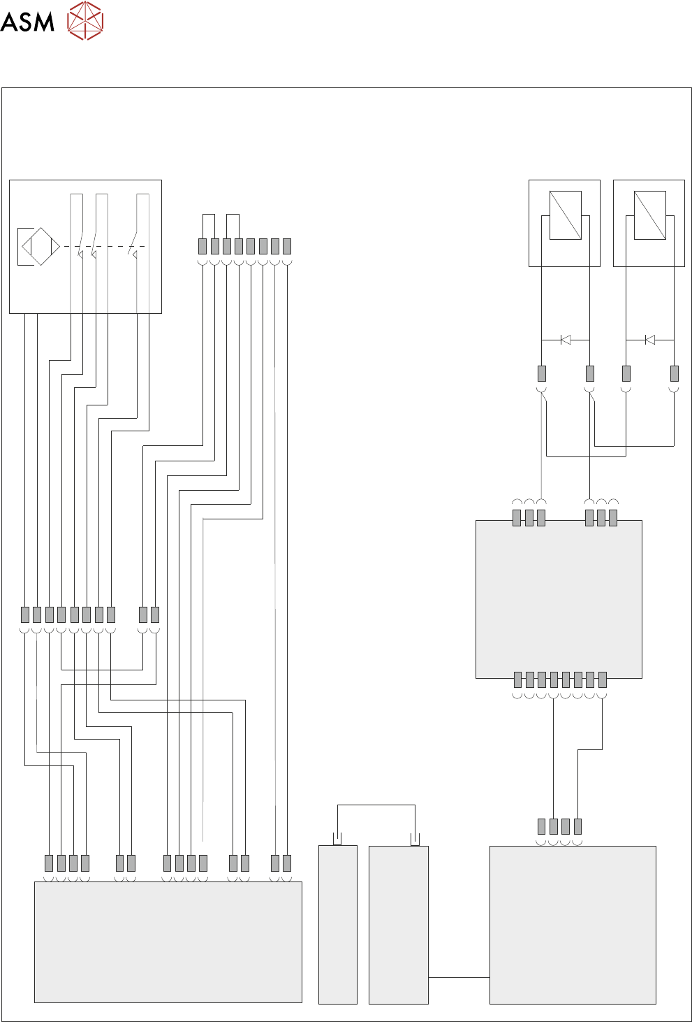
2.4 ELECTRICAL SCHEMATIC
Front
Cover
Magnetic
Coded
Safety
Switch
M71SW1
24V US
0V
M71 Power Supply
Enclosure
M71PL31
5SK33
APDSK2
APDSK1
5SK34
IO6
M71PL45
M71PL32
M71PL22
M71PL33
M71PL23
M71PL46
M71PL60
Front Cover
Lock LHS
5MAG2
Front Cover
Lock RHS
5MAG3
ESIO-5
Paste Dispenser
Safety Switch PCB
Machine Controller
Controller Power Module
(CPM)
Fibre
Optic
Links
SIO
Link
Cable
Single Cover
Blanking Plug
Cover Safety