88242361-04-01 Vol 1 DEK TQ TECHNICAL REFERENCE (1).pdfPDFA.pdf - 第20页
2 SAFETY FEATURES 2.4 ELECTRICAL SCHEMATIC 20 TECHNICAL REFERENCE MANUAL DEK TQ 04/2021 2.4 ELECTRICAL SCHEMATIC Front Cover Magnetic Coded Safety Switch M71S W1 24V U S 0V M71 Power Supply Enclosure M71P L31 5S K33 APDS…

2 SAFETY FEATURES
2.3 SAFETY CIRCUIT
TECHNICAL REFERENCE MANUAL DEK TQ 04/2021 19
2.3.3 Single Cover Machine
The single cover allows access to the print and tooling area and the paste dispenser, if fitted. The
cover has two electromagnetic locks one on the left edge and one on the right edge of the cover. A
single safety switch (located on the right hand side) monitors the position of the cover.
2.3.4 Dual Cover Machine
The dual cover machine has a front cover which allows access to the print, tooling, and paste dis-
penser areas. The front cover incorporates a sliding cover which allows access to the paste dis-
penser area only.
The paste dispenser cover can be slid open when the paste dispenser is at home position. This al-
lows the paste cartridge or paste jar to be replenished whilst the machine continues printing. During
paste dispensing, the paste dispenser cover is locked. Forcing the cover open during paste dis-
pensing will result in the system power (switched power) being dropped.
As the front cover incorporates the paste dispenser cover lifting the front cover also lifts the paste
dispenser cover.
Behind the paste dispenser cover are two electromagnetic locks. One electromagnet locks the front
cover and the other locks the paste dispenser cover.
2 SAFETY FEATURES
2.4 ELECTRICAL SCHEMATIC
20 TECHNICAL REFERENCE MANUAL DEK TQ 04/2021
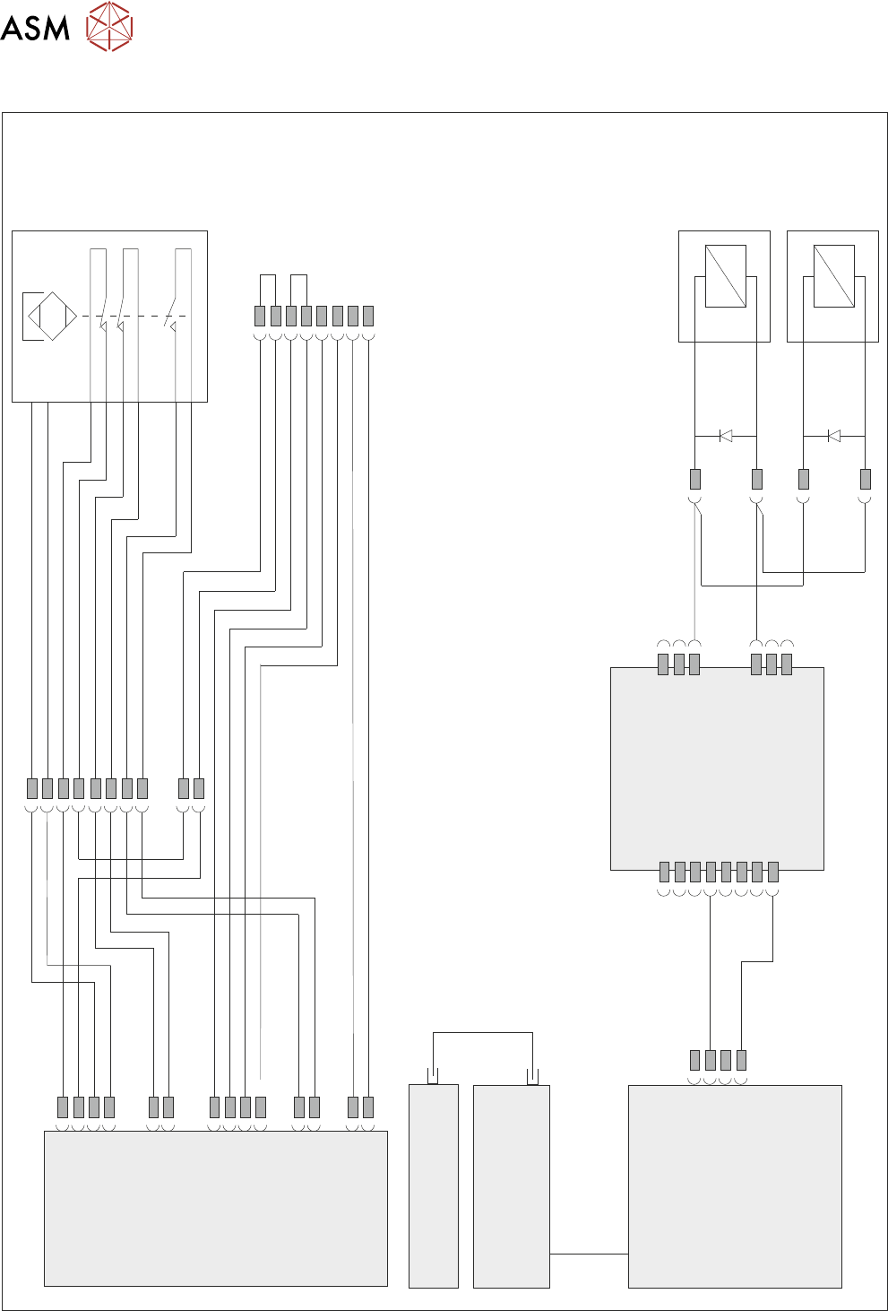
2.4 ELECTRICAL SCHEMATIC
Front
Cover
Magnetic
Coded
Safety
Switch
M71SW1
24V US
0V
M71 Power Supply
Enclosure
M71PL31
5SK33
APDSK2
APDSK1
5SK34
IO6
M71PL45
M71PL32
M71PL22
M71PL33
M71PL23
M71PL46
M71PL60
Front Cover
Lock LHS
5MAG2
Front Cover
Lock RHS
5MAG3
ESIO-5
Paste Dispenser
Safety Switch PCB
Machine Controller
Controller Power Module
(CPM)
Fibre
Optic
Links
SIO
Link
Cable
Single Cover
Blanking Plug
Cover Safety
2 SAFETY FEATURES
2.5 SAFETY LOCKOUT
TECHNICAL REFERENCE MANUAL DEK TQ 04/2021 21
2.5 SAFETY LOCKOUT
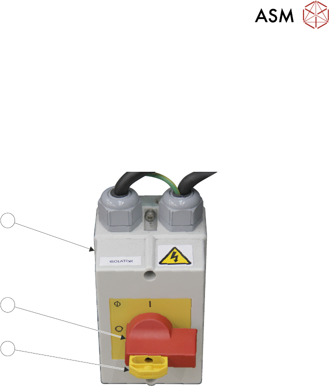
2.5.1 Electrical Lockout
Electrical lockout of the printer is achieved by applying a padlock, or any other suitable locking
device to the mains isolator switch. This can only be achieved when the mains isolator switch is in
the OFF
position.
To electrically lockout the printer, carry out the following procedure:
1. Close down the printer software.
2. Turn the mains isolator (3) switch (2) to the OFF position.
3
2
1
3. Pull the lockout tab (1) out.
4. Fit a padlock or suitable locking device through the hole in the lockout tab.
This prevents the isolator switch being turned to the On position and completes the electrical lock-
out.