88242361-04-01 Vol 1 DEK TQ TECHNICAL REFERENCE (1).pdfPDFA.pdf - 第43页
4 MACHINE OVERVIEW 4.1 MODULE OVERVIEWS TECHNICAL REFERENCE MANUAL DEK TQ 04/2021 43 4.1.10 Foreign Machine Interface (FMI) Module The FMI module, fitted behind the front panel, provides a communications link between upl…
4 MACHINE OVERVIEW
4.1 MODULE OVERVIEWS
42 TECHNICAL REFERENCE MANUAL DEK TQ 04/2021
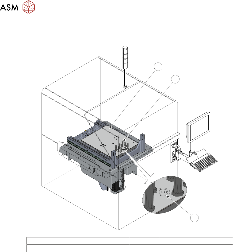
4.1.9 Tooling Table Module
The tooling table module provides a stable base for the board support tooling and positions the
table at various heights during the print cycle.
3
2
1
1 Tooling Table 3 Vacuum Tooling Port
2 Tooling
4.1.9.1 Tooling
The role of the tooling is to support the board during the print stroke, to prevent print distortion
caused by flexing of the board as a result of the downward pressure of the squeegees. Several dif-
ferent types of tooling are available including vacuum and dedicated tooling.
4.1.9.2 Vacuum Tooling Port
There is a vacuum port built into the table top for dedicated tooling and vacuum boxes.
4 MACHINE OVERVIEW
4.1 MODULE OVERVIEWS
TECHNICAL REFERENCE MANUAL DEK TQ 04/2021 43
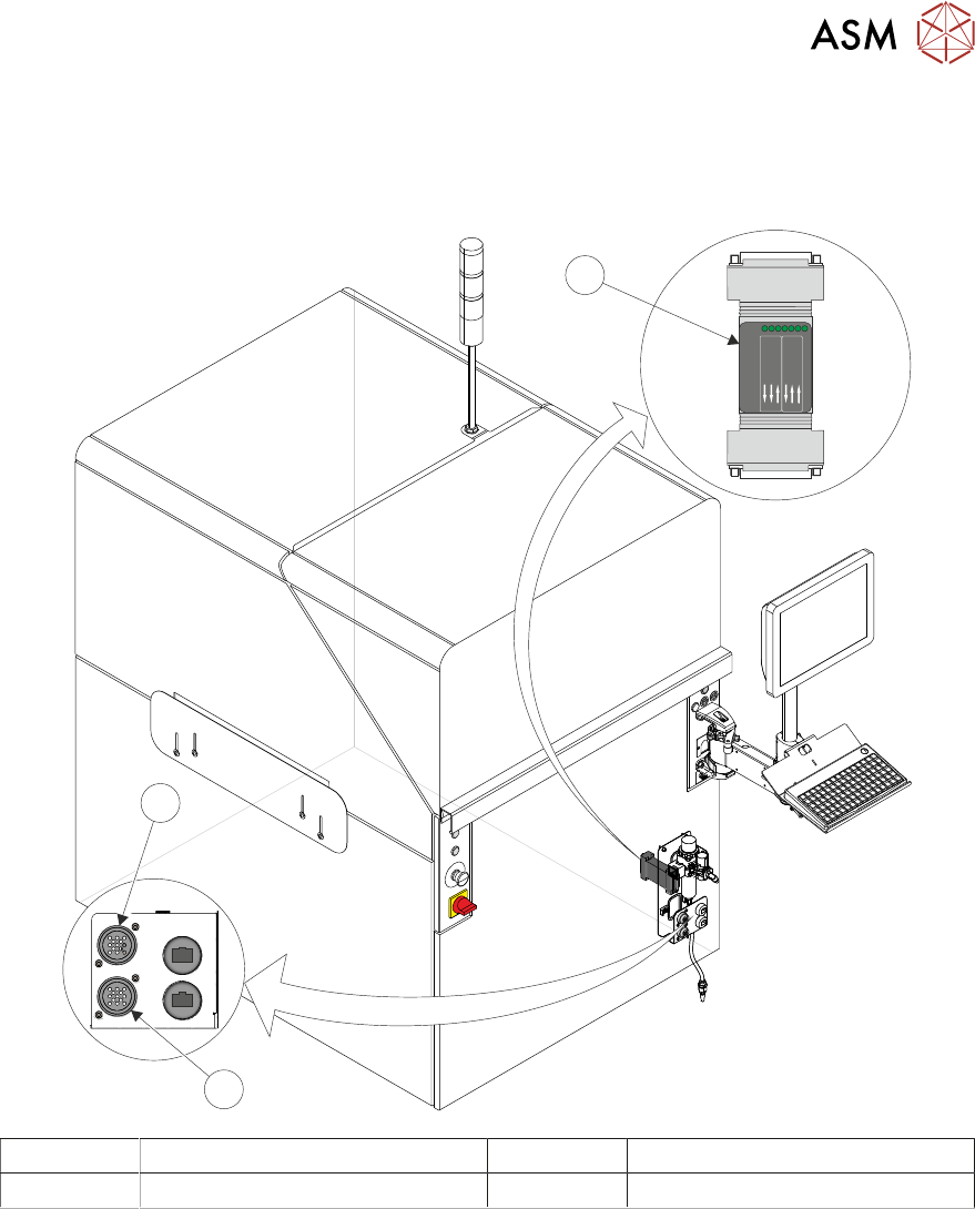
4.1.10 Foreign Machine Interface (FMI) Module
The FMI module, fitted behind the front panel, provides a communications link between upline/
downline machines and the DEK printer. The communication protocols include SMEMA, Fuji or
Panasonic interfaces.
POWER ON
PART No. 160740
M/C AVAI LABLE
BOAR D AVAILA BLE
BOAR D PASS
DOWNL INE
BOAR D AVAILA BLE
BOAR D PASS
M/C AVAI LABLE
UPLIN E
FMI POD
1
3
2
3
2
1
1 Foreign Machine Interface (FMI) 3 FMI Upline (Connected to 1)
2 FMI Downline (Connected to 1)

4 MACHINE OVERVIEW
4.2 MACHINE PRINT CYCLE
44 TECHNICAL REFERENCE MANUAL DEK TQ 04/2021
4.2 MACHINE PRINT CYCLE
The following is a typical print cycle when the machine is running in 3 stage mode, without an auto-
matic paste dispense or under stencil clean:
1. With the conveyors at transport height, a signal is sent to the upline machine to send a board.
2. A board (Board 1) is loaded on to the input auxiliary conveyor.
3. Once the centre section conveyor is available, the camera moves to the board stop position
and the board stop is extended.
4. Board 1 is driven on to the centre section to the board stop.
5. Board 2 is driven on to the input auxiliary conveyor.
6. The transport belts slow down as the board reaches the board stop.
7. Once at the board stop, the transport belts stop after a short delay.
8. The board stop moves away from the board and retracted.
9. The board is driven up to vision height.
10. The camera moves to the location of Fiducial 1 and captures the board and stencil fiducials.
11. The camera moves to the location of Fiducial 2 and captures the board and stencil fiducials.
12. The camera drives to its home position.
13. The chase clamps are de-energised.
14. Alignment of the stencil to the board is carried out using the information from Steps 10 and 11.
15. The chase clamps are re-applied.
16. The board is driven up to print height.
17. The squeegee drives down to print pressure.
18. The print carriage drives in the appropriate direction to perform a print stroke.
19. The squeegee drives to dwell height.
20. The board is lowered to transport height.
21. The board is moved to the output auxiliary conveyor if it is available.
22. The board count is incremented when the board leaves the centre section.
23. Board 2 is driven on to the centre section to the board stop.
24. Board 3 is driven on to the input auxiliary conveyor.
25. Board 1 is driven downline when the downline machine is available.