88242361-04-01 Vol 1 DEK TQ TECHNICAL REFERENCE (1).pdfPDFA.pdf - 第83页
6 MACHINE CONTROL 6.4 EXTENDED POWER MODULE (EPM) TECHNICAL REFERENCE MANUAL DEK TQ 04/2021 83 6.4 EXTENDED POWER MODULE (EPM) The EPM’s receive control signals from the CPM. The signals are directed to either a stepper …
6 MACHINE CONTROL
6.3 CONTROLLER POWER MODULE (CPM)
82 TECHNICAL REFERENCE MANUAL DEK TQ 04/2021
6.3.1.1 SIOLinks
SIOLInk Designation
SL1 ESIO-1 SL5 ESIO-5
SL2 ESIO-2 SL6 ESIO-6
SL3 ESIO-3 SL7 Spare
SL4 ESIO-4 SL8 Spare
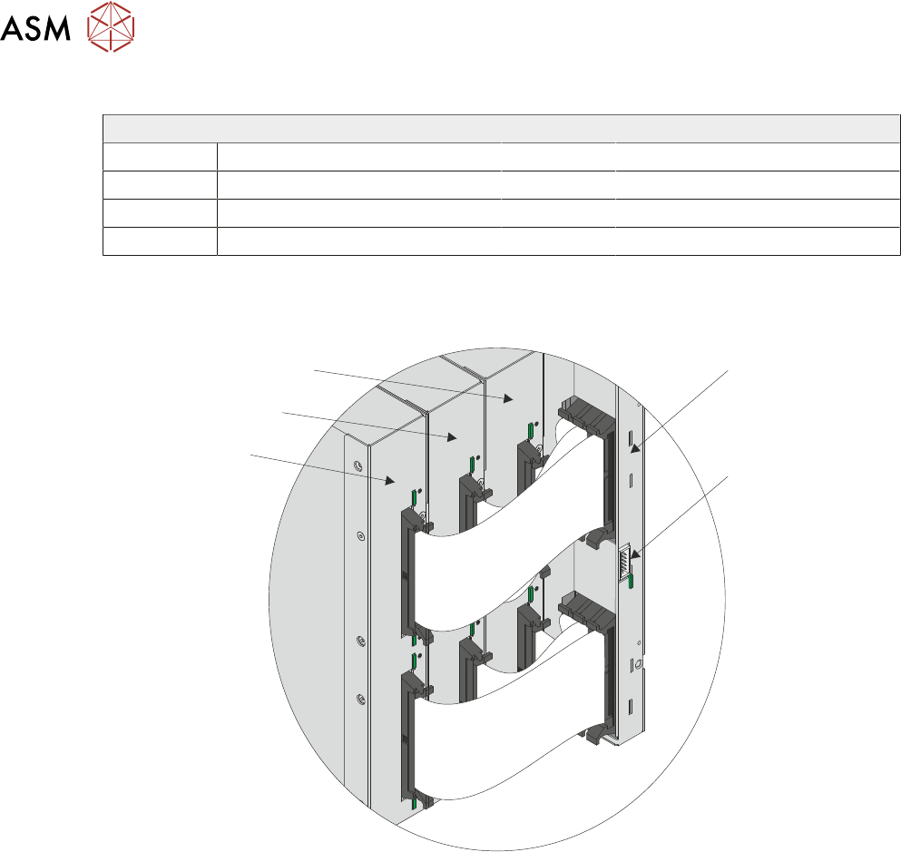
6.3.2 Rear Connectors
The rear of the CPM connects to the EPM’s using two ribbon cables to each EPM.
CPM
Not Used
EPM 1
EPM 2
EPM 3
View on Rear of CPM and EPM’s
6 MACHINE CONTROL
6.4 EXTENDED POWER MODULE (EPM)
TECHNICAL REFERENCE MANUAL DEK TQ 04/2021 83
6.4 EXTENDED POWER MODULE (EPM)
The EPM’s receive control signals from the CPM. The signals are directed to either a stepper or
servo drive card which connects directly to a motor.
Positional information of the motor (acquired from sensors or encoders) is fed back to the CPM via
the ESIO modules.
4
3
2
1
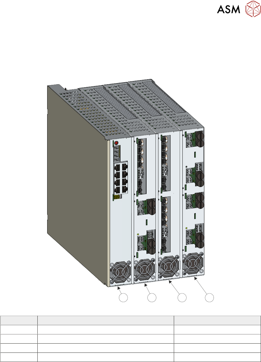
Item Description Driver Cards
1 Controller Power Module (CPM)
2 Extended Power Module (EPM) 1 1 Stepper and 1 Servo
3 Extended Power Module (EPM) 2 2 Stepper
4 Extended Power Module (EPM) 3 2 Servo
NOTE
EPM 1 is only fitted if auto coplanarity or TCM option is fitted.
In the circuit diagrams and schematics, the driver card designation reflects the EPM number plus
the position of the card. For example:
●
EPM3-1 = the drive card in the top position of EPM 3
●
EPM3-2 = the drive card in the bottom position of EPM 3
6 MACHINE CONTROL
6.4 EXTENDED POWER MODULE (EPM)
84 TECHNICAL REFERENCE MANUAL DEK TQ 04/2021
6.4.1 Stepper Drive Card
Stepper drive cards are used to drive the following stepper motors:
●
Transport Conveyors
●
Alignment Actuators
●
Coplanarity
●
Solvent Dispense
●
Paste Dispenser
●
Squeegees
●
Cleaner Fabric
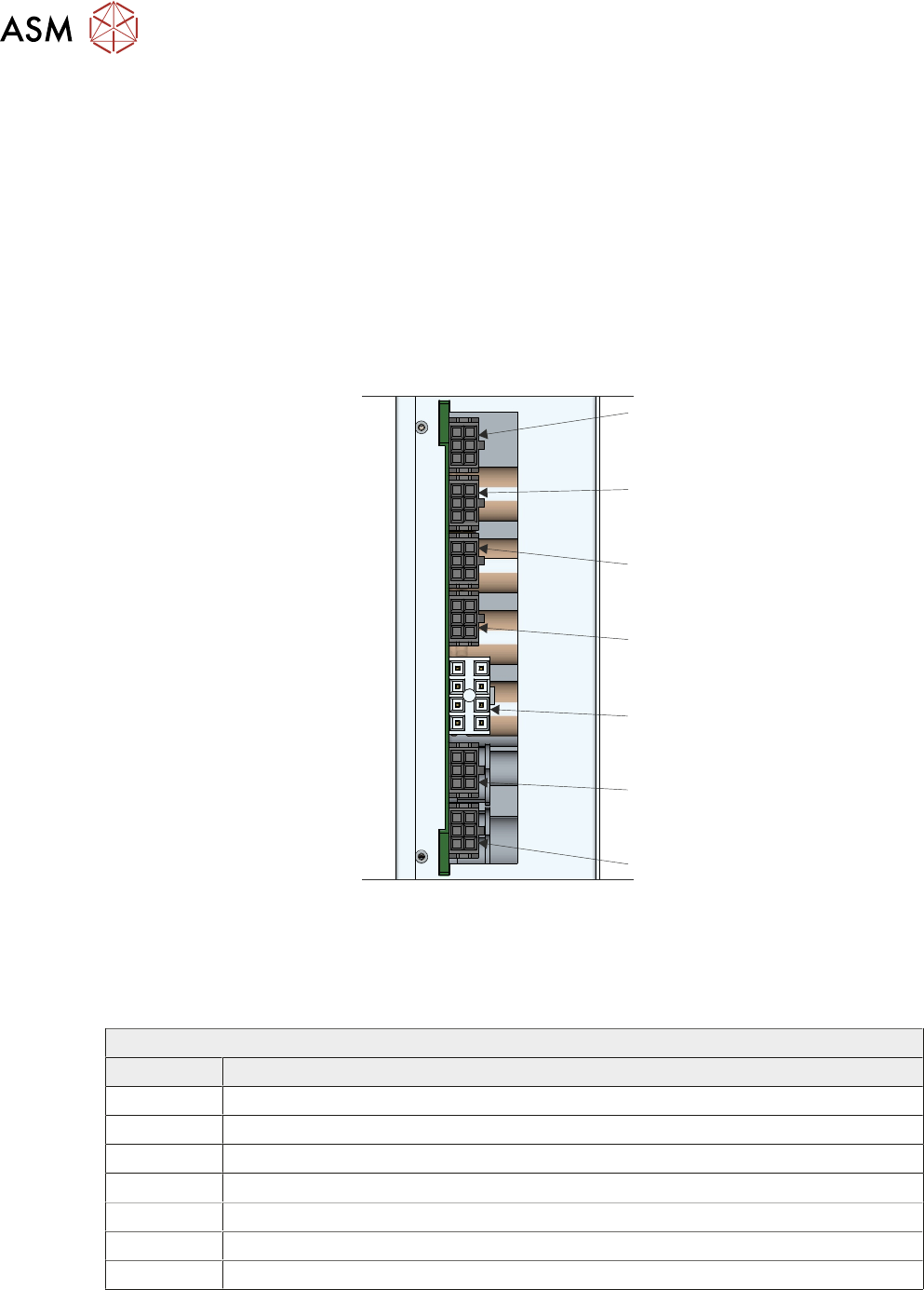
6.4.1.1 Connectors
J*-1
J*-2
J*-3
J*-4
J*-5
J*-6
J*-7
Stepper Drive Card Connectors
NOTE
J* is either J1 if the drive card is in the upper position (top) or J2 if in the lower position (bottom) of
the EPM.
EPM 1 Upper
Connector Description
J1-1 Spare
J1-2 Spare
J1-3 Spare
J1-4 Spare
J1-5 Power Input
J1-6 Coplanarity Motor Left (Option)
J1-7 Coplanarity Motor Right (Option)