00193361-01.pdf - 第20页
Retrofit Instructions Splice Detection Table Controller S / F 07/2002 Edition 20 ,QVW DOODWLRQ RI WKH 6 SOLFH 'HWHFWLRQ 7 DEOH &RQWUROOHU .LW : This kit requires changing out of th e stock controlle r…
Retrofit Instructions Splice Detection Table Controller S / F
07/2002 Edition
19
3UHSDUDWLRQV
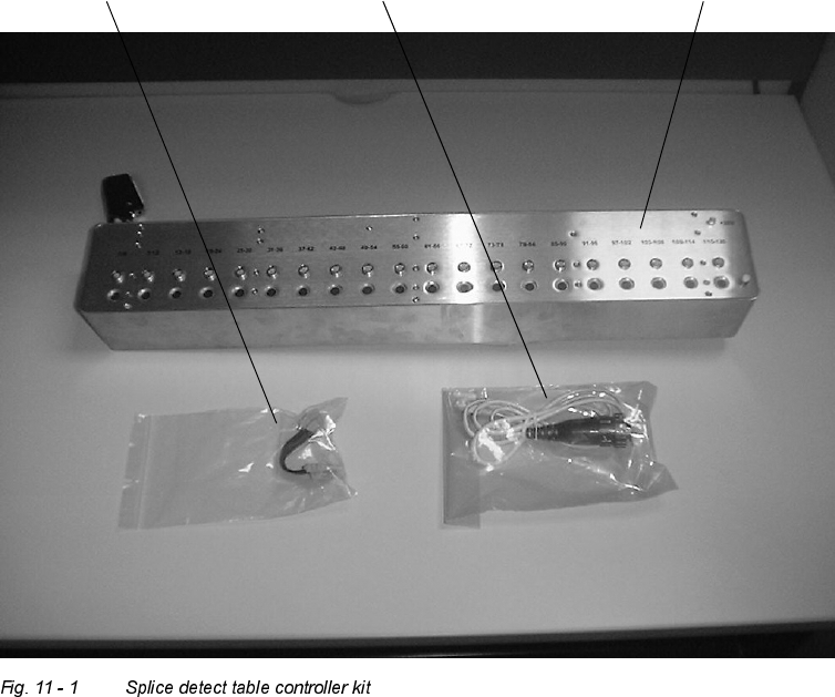
: Read All Installation Instructions, and become familiar with the Splice Detect Table Controller
Kit, shown in Fig. 11 - 1:
power supply adapter cat 5 cable table controller
Retrofit Instructions Splice Detection Table Controller S / F
07/2002 Edition
20
,QVWDOODWLRQRIWKH6SOLFH'HWHFWLRQ7DEOH&RQWUROOHU
.LW
: This kit requires changing out of the stock controller module with the new module. There are
several different mounting methods for the OEM table controller and the subsequent Splice De-
tect Table Controller will mount in the identical fashion as the original.
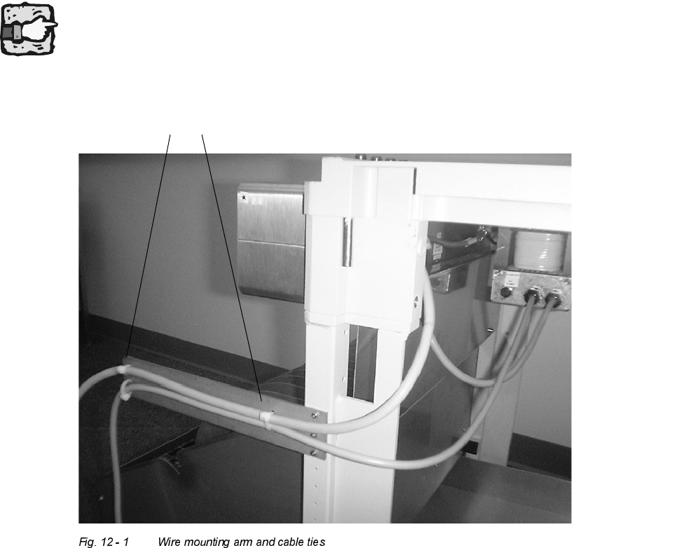
: On the right side of the feeder table, cut the tie straps that hold the existing cable to the formed
metal extension arm (see Fig. 12 - 1).
Depending on the version of the table the cables are fixed in a U-profile. In this case please cut
the tie straps and loosen the cables in the same way.
existing cable wire ties
Retrofit Instructions Splice Detection Table Controller S / F
07/2002 Edition
21
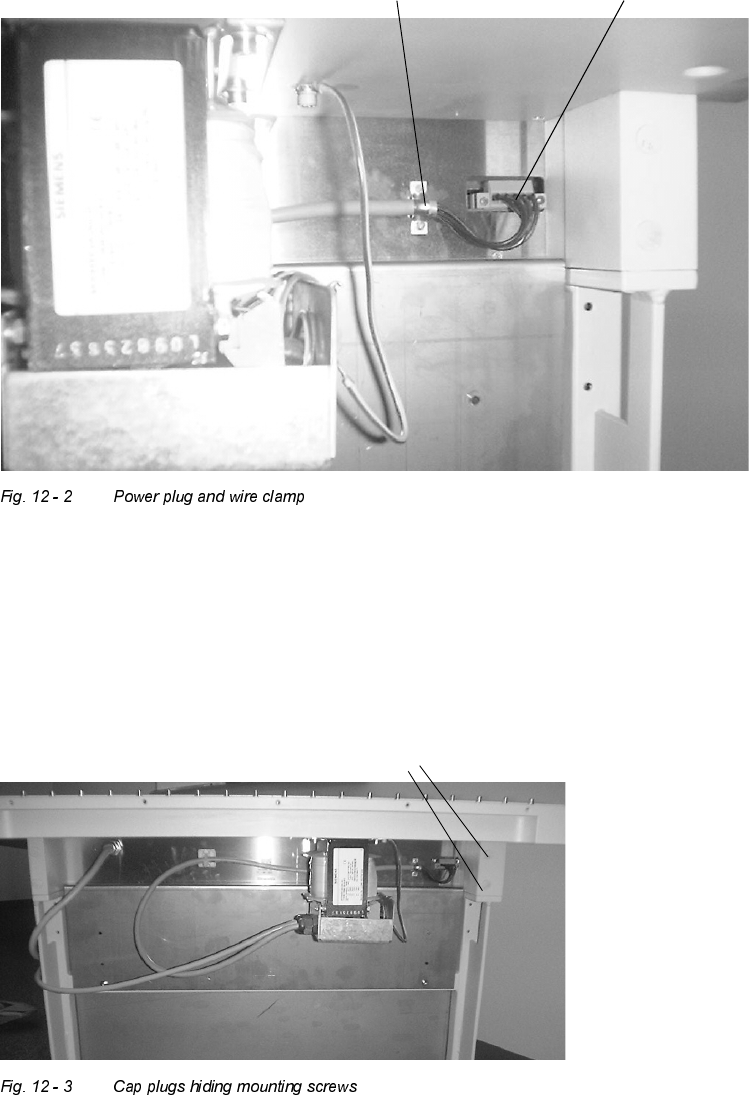
: At the back right corner of the OEM controller, unplug the orange power connector plug that
plugged into the controller. Also use the flat blade screwdriver to remove the two wire clamp
screws that attach this wire to the back of the existing box, as shown in Fig. 12 - 2.
: When dealing with the feeder table that has mounting holes through the riser blocks, remove
the cap plugs (see Fig. 12 - 3) that hide the 4 table controller mounting bolts. Remove the four
mounting bolts while holding or supporting the box in the front to prevent the existing box from
falling.
: Install the new box using the existing hardware in a similar fashion.
Wire clamp Power plug
Cap plugs