3OM-1011-001.pdf - 第249页
Note: When the front-lighting system is used to recognize square and deform components, the word “EDGE” is changed to “ELECTRICAL CONT ACT”. (Cause 1) An improper vacuum nozzle is selected for the component or vice versa…
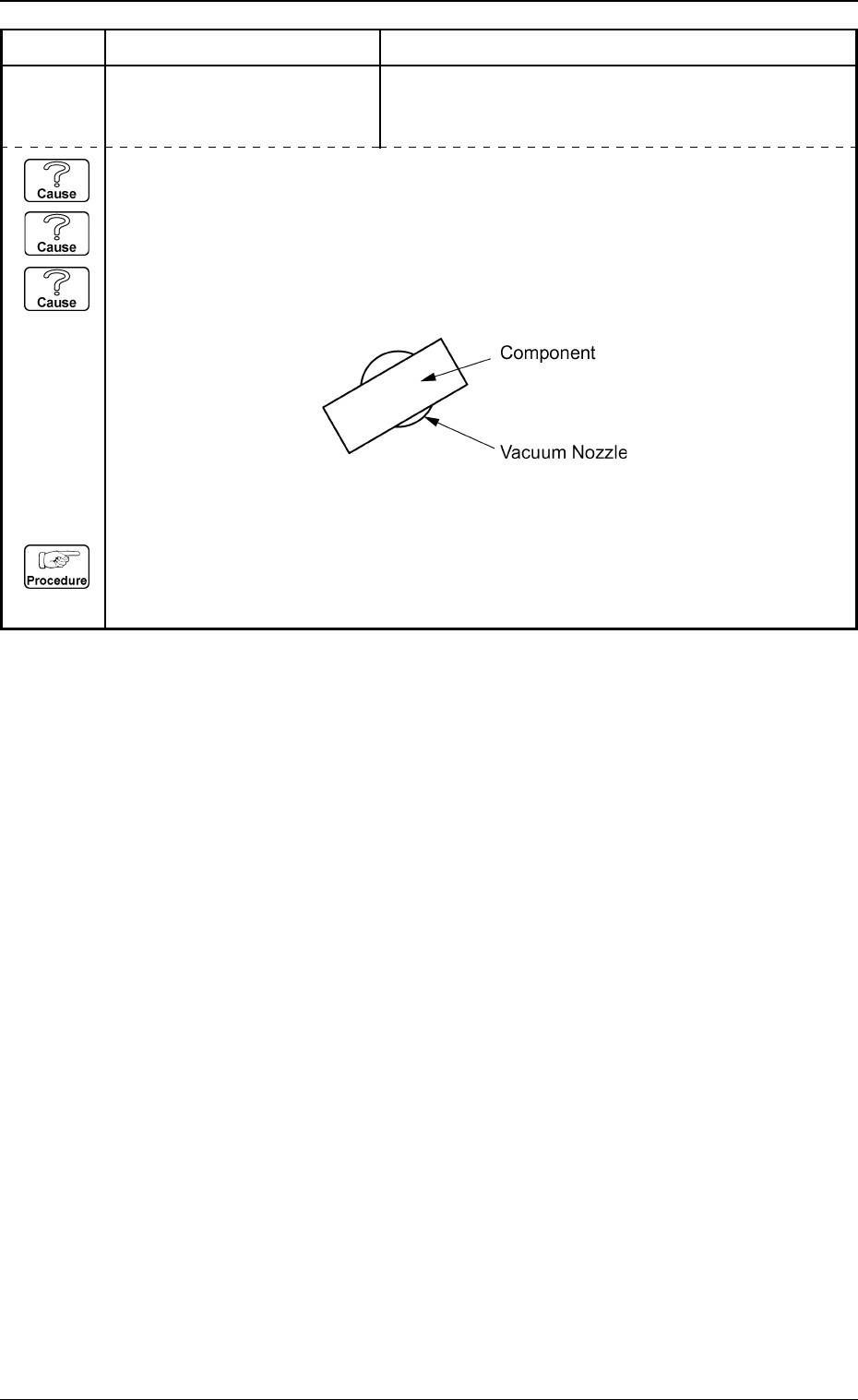
(Cause 1) An improper vacuum nozzle is selected for the components or vice versa.
(Cause 2) The component is bent due to weak vacuum suction force.
(Cause 3) When a component is picked up, the pick-up positions (X and Y) and angle have
shifted greatly from the correct ones.
(Reset Procedure in the case of Causes 1, 2 and 3)
Reset Procedure
(1) Check the selected component and vacuum nozzle.
(2) Check the vacuum pressure.
5. Component Recognition Error Code and List of Error Messages
0305-001 4-43 Tg0859-PM-ER
Error Code Display A Display B
2032X001 ANGLE DETECTION ERROR
Note: X represents “1 through
4, 8 and 9”.
RECOGNITION ABORTED BECAUSE OF IMPROPER
COMPONENT HANDLING.
Fig. 3D4
Note: When the front-lighting system is used to recognize square and deform components, the
word “EDGE” is changed to “ELECTRICAL CONTACT”.
(Cause 1) An improper vacuum nozzle is selected for the component or vice versa.
(Cause 2) Wrong parameters (edge data) are set for the selected component in the component
library data.
(Cause 3) Wrong parameters are set for the component outward length X, Y and tolerance of the
selected component.
(Cause 4) An improper parameter is set in the "DIRECTION" data box of the label "LEAD
DATA".
(Cause 5) The pick-up position is shifted too much.
(Reset Procedure in the case of Causes 1, 2, 3, 4 and 5)
Reset Procedure
(1) Check the selected component and the vacuum nozzle.
(2) Check if the feeder (B) offset data is correct.
(3) Check the edges of the selected component and the parameters set as “EDGE DATA” in the
component library data.
(4) If wrong parameters are set in the component library data, correct them.
5. Component Recognition Error Code and List of Error Messages
Error Code Display A Display B
0305-001 4-44 Tg0859-PM-ER
2033Y010 EDGE DETECTION ERROR
to 019 Note:Y represents “1”, “2”, or
“4”.
NOZZLE PROTRUSION PRESENTS ON SOME
EDGES.
Note: When the front-lighting system is used to recognize square and deform components, the
word “EDGE” is changed to “ELECTRICAL CONTACT”.
(Cause 1) An improper vacuum nozzle is selected for the component or vice versa.
(Cause 2) Wrong parameters (edge data) are set for the selected component in the component
library data.
(Cause 3) Improper parameters are set in the "DETECT X POSN" and "DETECT Y POSN" data
boxes.
(Cause 4) Dirt and dust, etc., have adhered to the nozzle diffusion plate and the head lighting unit
in the vicinity of the edges.
(Reset Procedure in the case of Causes 1, 2, 3 and 4)
Reset Procedure
(1) Check the selected component and the vacuum nozzle.
(2) Check if the feeder (B) offset data is correct.
(3) Check the edges of the selected component and the parameters set as “EDGE DATA” in the
component library data.
(4) If wrong parameters are set in the component library data, correct them.
5. Component Recognition Error Code and List of Error Messages
Error Code Display A Display B
0305-001 4-45 Tg0859-PM-ER
2033Y100 EDGE DETECTION ERROR
to 109 Note:Y represents “1”, “2”, or
“4”.
EDGE (UPPER) NOT FOUND.
2033Y300 EDGE DETECTION ERROR
to 309 Note:Y represents “1”, “2”, or
“4”.
EDGE (RIGHT) NOT FOUND.
2033Y400 EDGE DETECTION ERROR
to 409 Note:Y represents “1”, “2”, or
“4”.
EDGE (LOWER) NOT FOUND.
2033Y200 EDGE DETECTION ERROR
to 209 Note:Y represents “1”, “2”, or
“4”.
EDGE (LEFT) NOT FOUND.