3OM-1011-001.pdf - 第28页
Check whether a problem has arisen in the condition of P .C.B. surfaces. *5 Check for ragged P .C.B. surfaces and warping. Especially , a warped P .C.B. may bound and cause components to de- viate from the correct positi…
Check whether the head rotational shaft rotates smoothly. *9
Confirm that the head rotational shaft rotates smoothly when turned
by hand.
Check whether the placement level is correct. *10
When a component is excessively pushed for placement or the vacuum
turns off before a component reaches the placement surface, it will be
placed incorrectly, deviating from the correct placement position.
Check the offset in the vertical (height) direction and the height data
in the component library data.
Check whether the device offset data is proper. *11
If the device offset data is not normal, component cannot be picked
up nor placed correctly.
Open the “OFFSET DATA” display and check each offset data. (Hi-
erarchical Sequence: “DATA EDIT” Display → “OFFSET DATA”
Display)
Open the “MANUAL SUBSYSTEM OPERATION” and “DEVICE
TEST” displays and check visually that each device moves to its cor-
rect position.
Note: Although each offset data can be taught at the “OFFSET
TEACH” display, it is required to re-teach a series of device
offset data. (Hierarchical Sequence: “SPECIAL SEL.” Dis-
play → “OFFSET TEACH” Display)
A special jig is also required for the teaching operations.
Whenever it is necessary to perform the teaching operations,
consult our sales personnel for details.
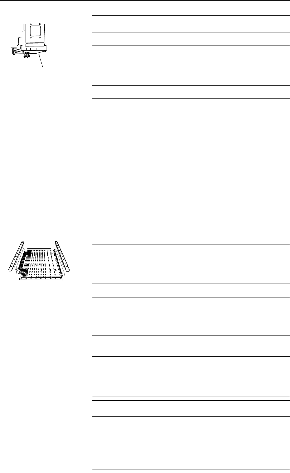
Check whether P.C.B. support pins are correctly set. *1
Check visually whether no problem has arisen in the location of the
P.C.B. support pins.
Especially, when components are placed on both sides of a P.C.B.,
confirm that no component on the back of the P.C.B. touches any
P.C.B. support pin.
Check whether the P.C.B. supporting plate moves normally. *2
Check visually whether no problem has arisen in the movement of
the P.C.B. supporting plate.
When the P.C.B. supporting plate does not move up (pushing) nor-
mally, a P.C.B. may deviate from its correct position during compo-
nent placement.
Check whether the set parameter as the conveyor width (com-
pared with the P.C.B. width) is correct. *3
If the conveyor width is not proper, P.C.B.’s cannot be transferred
smoothly, causing wrong P.C.B. positioning or positional deviation
of a P.C.B. due to vibrations (caused during placement).
Or, P.C.B.’s may not be pushed horizontally enough or positioned
correctly, causing positional deviation of a P.C.B. during placement.
Check whether the groove of the fixed chute or the bearing of the
movable chute is under abnormal condition. *4
If a foreign substance exists in the groove of the fixed chute, P.C.B.’s
cannot be positioned correctly, causing positional deviation of place-
ment. If a foreign substance is found in the groove of the fixed chute
or the bearing of the movable chute during P.C.B. transfer does not
work smoothly, P.C.B.’s cannot be transferred, causing wrong P.C.B.
positioning or positional deviation of a P.C.B. due to vibrations (caused
during placement).
*9
1.2.2 Deterioration of Accuracy in P.C.B. Positioning Section,
User Production P.C.B.’s, and Transfer Section
0305-001 1-14 Tg0859-PM-ER
1.2 Countermeasures against Deterioration of Placement Accuracy
Fig. 3A20
Fig. 3A21
Check whether a problem has arisen in the condition of P.C.B.
surfaces. *5
Check for ragged P.C.B. surfaces and warping.
Especially, a warped P.C.B. may bound and cause components to de-
viate from the correct position during component placement.
Check whether the quantity of glue and solder paste is proper.
*6
If the quantity of glue and solder paste is insufficient, components
cannot be placed securely, causing dislocation of components.
On the other hand, if the quantity is excessive, component may also
be dislocated because the placement plane differs in height.
Check whether the positional relation between glue or solder paste
and components is appropriate. *7
Check P.C.B.’s after component placement. If placement position has
deviated from the correct one in comparison with the patterns, cor-
rect the placement coordinates.
Check whether there is a factor that may cause vibration and
shock while a component placed P.C.B. is being transferred. *8
If the P.C.B. transfer chute is under abnormal condition, P.C.B.’s can-
not be transferred smoothly, causing positional deviation of place-
ment. If a P.C.B. is given a big shock while being pushed against the
P.C.B. stopper in the output machine, placed components may devi-
ate from the correct position.
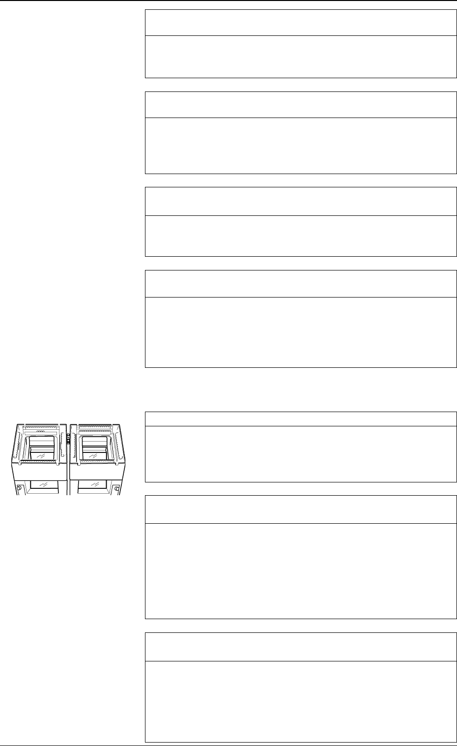
Check for dust and dirt on the lenses. *1
Dust and dirt accumulated on the lenses may cause false recognition
frequently.
Check that dust and dirt are not included in the captured images.
If necessary, clean the lenses with a lens cleaner.
Check whether the lamps for component recognition are “ON”
normally. *2
Open the “COMPONENT RECOG LIGHTING” display and turn on
the lamps for component recognition. (Hierarchical Sequence: “SPE-
CIAL SEL.” Display → “UNIT ADJUSTMENT” Display → “REC-
OGNITION LIGHTING” Display → “COMPONENT RECOG
LIGHTING” Display)
Confirm that each unit for component recognition lighting illumi-
nates.
Check whether the parameters in the component library data are
set properly. *3
When appropriate parameters such as size and lighting are not set in
the component library data, false component recognition and posi-
tional deviation will occur frequently.
Make a component recognition test and check whether or not the pa-
rameters such as size and lighting are correctly set in the component
library data.
1.2.3 Deterioration of Accuracy at Component Recognition
Camera Section
0305-001 1-15 Tg0859-PM-ER
1.2 Countermeasures against Deterioration of Placement Accuracy
Fig. 3A22
Check whether a problem has arisen in the offset of the compo-
nent recognition camera. *4
If the offset has a problem, the component recognized by the camera
will deviate from the correct position when placed.
Confirm that the offset data of the component recognition camera is
correctly set.
Note: Although the offset data of the component recognition cam-
era can be taught at the “OFFSET TEACH” display, it is
required to re-teach a series of device offset data. (Hierarchi-
cal Sequence: “SPECIAL SEL.” Display → “OFFSET
TEACH” Display)
A special jig is also required for the teaching operations.
Whenever it is necessary to perform the teaching operations,
consult our sales personnel for details.
Check whether fiducial marks are proper in size. *1
If the set mark does not match the actually captured image in size, it
will result in false recognition, positional deviation, etc.
Check whether the set mark is proper in size.
Check for dust and dirt on the lenses. *2
Dirt and dust accumulated on the lenses may cause false recognition
frequently.
Check that dirt and dust are not included in the captured images.
If necessary, clean the lenses with a lens cleaner.
Check whether the gain and level offset data for the P.E.C. cam-
era is proper, using an actual P.C.B. (P.C.B. on which component
are actually placed). *3
It is required to check the gain and level offset data for the P.E.C.
camera every time the current program is changed to another one.
The gain and level may also differ depending on each production lot
of P.C.B.’s.
Make a P.E.C. recognition test and confirm that P.C.B.’s can be rec-
ognized normally.
If the contrast between the mark and the background is not sufficient,
stable recognition cannot be expected.
While changing the gain and level data, check how the recognition is
made and determine appropriate parameters which enable stable rec-
ognition. Then, enter the parameters in the device offset data.
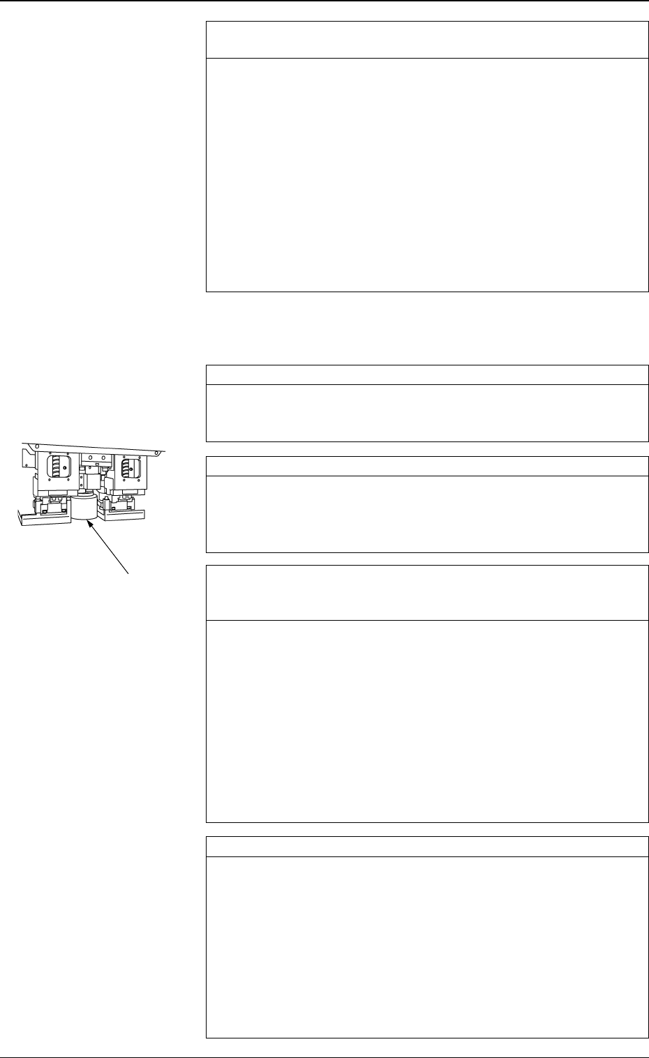
Check whether the lamps for P.E.C. recognition are “ON”. *4
Check whether the power voltage for lighting is proper.
Open the "P.E.C. RECOG LIGHTING" display and turn on the lamps
for P.E.C. recognition. (Hierarchical Sequence: “SPECIAL SEL.”
Display → “UNIT ADJUSTMENT” Display → “RECOGNITION
LIGHTING” Display → “P.E.C. RECOG LIGHTING” Display)
(Perform the checking for both “CAM-A3” and “CAM-B3”.)
• Confirm that the lamps for P.E.C. recognition lighting are “ON”.
• Confirm that the output voltages of power supply “G21” and “G22”
on Beams A and B are 5.0 ± 1.0 V when the lamps for P.E.C.
recognition are “ON”.
*2
1.2.4 Deterioration of Accuracy in P.E.C. Recognition
Camera Section
0305-001 1-16 Tg0859-PM-ER
1.2 Countermeasures against Deterioration of Placement Accuracy
Fig. 3A23