SIPLACE X-Series (SIPLACE X-Series S, from SC 708.1) Edition 05/2015 EN User manual.pdf - 第134页
3 Technical data and assemblies User manual SIPLACE X-Series 3.5 Placement head From software version 708.1 Version 05/2015 134 3.5.3.1 Description The SIPLACE S peedSt ar (C&P20 P) functions according to the Co llec…
User manual SIPLACE X-Series 3 Technical data and assemblies
From software version 708.1 Version 05/2015 3.5 Placement head
133
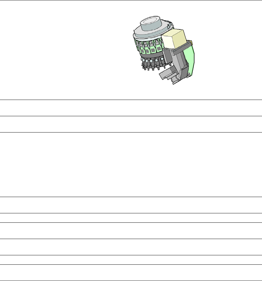
3.5.3 SIPLACE SpeedStar C&P20 P for very high speed placement
3
3
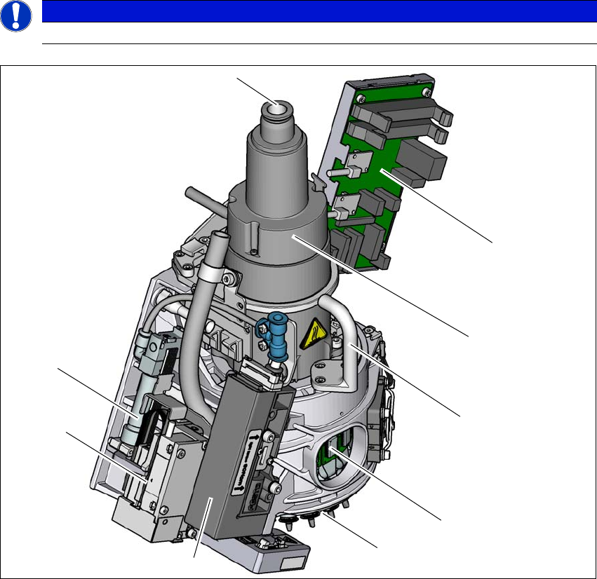
Fig. 3.5 - 5 SIPLACE C&P20 P - overview
(1) Compressed air connection for 20 Venturi nozzles in the pickup/placement and holding circuit
(2) "Vacuum sensor hold circuit" board
(3) Star motor
(4) Handle
(5) DP drive, 20 drives
(6) Star with 20 nozzles
(7) Pressure control valve
(8) Z motor (linear motor)
(9) Return cylinder
PLEASE NOTE
Available from software version SC.707.1
(5)
(1)
(7)
(2)
(3)
(4)
(6)
(8)
(9)
3 Technical data and assemblies User manual SIPLACE X-Series
3.5 Placement head From software version 708.1 Version 05/2015
134
3.5.3.1 Description
The SIPLACE SpeedStar (C&P20 P) functions according to the Collect&Place principle, i.e.
twenty components are picked up by the placement head within a single cycle. At the pick-up and
placement position the component sensor checks that the component is present at the nozzle. On
their way to the placement position the components are optically centered and rotated into the re-
quired placement angle. Finally forced air sets down the component gently and accurately on the
board.
The placement performance has been enhanced even more with the introduction of the C&P20 P
placement head. The compact design of the C&P20 P head also facilitates very short cycle times.
In this case, the star axis is at an angle to the PCB level. This geometry allows the segments to
be arranged in a very small space.
The component camera is still integrated into the C&P20 P head. This saves additional traveling
distances to external centering cameras. Each segment also has its own DP drive for rotating the
nozzle. The nozzles are therefore no longer rotated into the correct position at a single head sta-
tion. They can be rotated into their placement position at any time and independently of one an-
other.
Each segment has a separate vacuum generator. This greatly reduces the time taken to switch
between vacuum and air kiss. It also allows a vacuum check to be carried out in the holding circuit
for each individual nozzle.
The Z drive for the segments is implemented with a linear motor with linear path measuring sys-
tem, and is thus extremely precise. In the pick-up/placement position, the Z drive moves the seg-
ments up or down in the vertical direction.
User manual SIPLACE X-Series 3 Technical data and assemblies
From software version 708.1 Version 05/2015 3.5 Placement head
135
3.5.3.2 Technical data SIPLACE SpeedStar (C&P20 P)
3
SIPLACE SpeedStar (C&P20 P)
with component camera
type 23
with component camera type 41
Component range
*a
*)a Please note that the placeable component range is also affected by the pad geometry, the customer-spe-
cific standards, the component packaging tolerances and the component tolerances.
01005 to 2220, Melf, SOT,
SOD
03015 mmto 2220, Melf, SOT,
SOD, Bare-Die, Flip-Chip
Component spec.
Max. height
Min. lead pitch
Min. lead width
Min. ball pitch
Min. ball diameter
Min. dimensions
Max. dimensions
Max. weight
4 mm
0.25 mm
0.1 mm
0.4 mm
0.2 mm
0.4 mm x 0.2 mm
6 mm x 6 mm
1 g
4 mm
0.08 mm
0.03 mm
0.10 mm
0.05 mm
0.12 mm x 0.12 mm
6 mm x 6 mm
1 g
Programmable set-down
force
1.3 - 4.5 N 1.3 - 4.5 N
Nozzle types 40xx 40xx
X/Y accuracy
*b
*)b The SIPLACE benchmark value is measured during the machine acceptance tests. It corresponds to the
conditions set out in the SIPLACE scope of service and supply.
± 36 µm/3σ
± 48 µm/4σ
± 36 µm/3σ
± 48 µm/4σ
Angular accuracy ± 0.5° / 3σ
± 0.7° / 4σ
± 0.5° / 3σ
± 0.7° / 4σ
Illumination level 5 5
Possible illumination
level settings
256
5
256
5