SIPLACE X-Series (SIPLACE X-Series S, from SC 708.1) Edition 05/2015 EN User manual.pdf - 第156页
3 Technical data and assemblies User manual SIPLACE X-Series 3.6 Gantry system From software version 708.1 Version 05/2015 156 3.6.6 T echnical data for X axis SIPL ACE X2 S / X3 S / X4 S / X4i S 3 3.6.7 T echnical data …
User manual SIPLACE X-Series 3 Technical data and assemblies
From software version 708.1 Version 05/2015 3.6 Gantry system
155
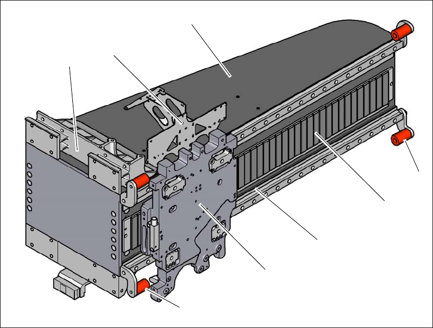
3.6.5 X axis structure
3
Fig. 3.6 - 5 Design of X axis - view of head mount
(1) Head mount with X axis linear motor (primary part)
(2) Y linear motor with fixed bearing (primary part)
(3) Guidance system with permanent magnet (secondary part of the X linear motor)
(4) End position bumper (4x)
(5) Gantry arm
(6) Head board mount
(7) Length measurement system
The gantry arm is made of a carbon fiber composite. This technology allows assemblies to be
made with extremely low weight and high rigidity.
The X axis is driven by a linear motor. The secondary part of the drive consists of a permanent
magnet and is mounted on the gantry arm. The primary part is bolted to the head mount. The head
mount has been designed so that all placement head types can be accommodated - one of the
benefits of the great flexibility in the SIPLACE machines.
(4)
(3)
(1)
(5)
(2)
(6)
(4)
(7)

3 Technical data and assemblies User manual SIPLACE X-Series
3.6 Gantry system From software version 708.1 Version 05/2015
156
3.6.6 Technical data for X axis SIPLACE X2 S / X3 S / X4 S / X4i S
3
3.6.7 Technical data for X axis SIPLACE X4 S micron / X4i S micron
3
Drive Linear motor (primary drive)
Max. speed 2.5 m/s
Distance measuring system Linear metal scale
Resolution 1 µm
Drive Linear motor (primary drive)
Max. speed 2.5 m/s
Distance measuring system Linear metal scale
Resolution 0.5 µm

User manual SIPLACE X-Series 3 Technical data and assemblies
From software version 708.1 Version 05/2015 3.6 Gantry system
157
3.6.8 Y axis structure
3
Fig. 3.6 - 6 Y-axis structure (example of SIPLACE X2 S / X3 S / X4 S shown)
The Y axis essentially consists of the following main modules:
(1) Y linear motors (primary part) on the X axis with fixed and loose bearing mounted
(2) Permanent magnet (secondary part of the X-axis linear motor)
(3) Linear distance measuring system
(4) Guidance system
(1)
(4)
(2)
(3)
(4)