SIPLACE X-Series (SIPLACE X-Series S, from SC 708.1) Edition 05/2015 EN User manual.pdf - 第159页
User manual SIPLACE X-Series 3 Technical data and assemblies From software version 708.1 Version 05/2015 3.7 PCB conve yor system 159 3.7 PCB conveyor system 3.7.1 Description The PCB conv eyors have a five-part design, …

3 Technical data and assemblies User manual SIPLACE X-Series
3.6 Gantry system From software version 708.1 Version 05/2015
158
3.6.9 Technical data for Y axis SIPLACE X2 S / X3 S / X4 S / X4i S
3
3.6.10 Technical data for Y axis SIPLACE X4 S micron / X4i S micron
3
Drive Linear motor (primary drive)
Max. speed 2.5 m/s
Distance measuring system Linear metal scale
Resolution 1 µm
Drive Linear motor (primary drive)
Max. speed 2.5 m/s
Distance measuring system Linear metal scale
Resolution 0.5 µm
User manual SIPLACE X-Series 3 Technical data and assemblies
From software version 708.1 Version 05/2015 3.7 PCB conveyor system
159
3.7 PCB conveyor system
3.7.1 Description
The PCB conveyors have a five-part design, comprising input conveyor, placement area 1, inter-
mediate conveyor, placement area 2 and output conveyor. The three areas input conveyor, inter-
mediate conveyor and output conveyor serve as buffer zones for the printed circuit boards.
The conveyor belts are driven by brushless DC motors. Light barriers monitor and control trans-
portation of the boards. Once the board has reached the placement area and has passed the light
barriers, it is braked. A laser light barrier records the position of the board. As soon as the circuit
board has reached its target position, the conveyor belt is stopped and the board is clamped from
below.
The distance between the top of the PCB and the placement head thus remains unchanged for
each PCB, and is not dependent on the thickness of the PCB. The placement rate is thus inde-
pendent of the PCB thickness. The PCB fiducial centering can also be optimized. Since the dis-
tance between the PCB surface and the PCB camera remains the same, the PCB camera is
always focussed on the PCB surface with the same sharpness. The PCB fiducial contours are op-
timally mapped on the CCD chip of the PCB camera.
The width of the circuit board conveyor is set and monitored by an integral control circuit. It can
be selected by calling up the program. The control electronics activate the drive motor until the
required width has been reached. The width adjustment is therefore independent of other machine
components.
The conveyor height can be selected on the machine to allow the machines to be integrated into
lines with a conveyor height of, 900, 930 or 950 mm. The standard height is 930 mm.
The PCB conveyors communicate with the individual machines via the SMEMA interface or the
optional Siemens interface.
3 Technical data and assemblies User manual SIPLACE X-Series
3.7 PCB conveyor system From software version 708.1 Version 05/2015
160
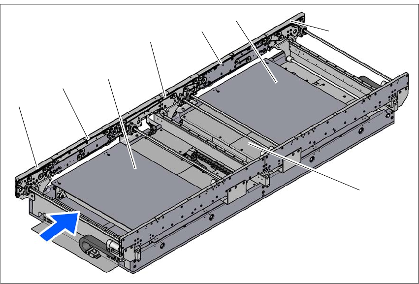
3.7.2 Design of the PCB single conveyor
The fixed conveyor side can be selected either on the right or left in single conveyors. The position
of the fixed side can be set according to the specifications.
3
Fig. 3.7 - 1 Design of the PCB single conveyor
(1) Input conveyor
(2) Conveyor lane 1
(3) Lifting table 1
(4) Intermediate conveyor
(5) Conveyor lane 2
(6) Lifting table 2
(7) Output conveyor
(8) Conveyor control (under the cover)
(4)
(1)
(2)
(3)
(5)
(6)
(8)
(7)