SIPLACE X-Series (SIPLACE X-Series S, from SC 708.1) Edition 05/2015 EN User manual.pdf - 第18页
1 Introduction User manual SIPLACE X-Series 1.1 Machine overview From software version 708.1 Version 05/2015 18 1.1 Machine overview 1.1.1 SIPLACE X4 i S 1 Fig. 1.1 - 1 SIPLACE X4i S placement machine The SIPLACE X4i S p…

User manual SIPLACE X-Series 1 Introduction
From software version 708.1 Version 05/2015
17
1 Introduction
This user manual is a guide or reference work for operating and setting up the
SIPLACE
®
X-Series S placement machines.
The X-Series S placement machines are available in six different variants.
– SIPLACE X4i S
–SIPLACE X4 S
– SIPLACE X4i S micron
– SIPLACE X4 S micron
–SIPLACE X3 S
–SIPLACE X2 S
The numbers in the type name indicate the number of gantries used. Each gantry has one place-
ment head.
This document is the original user manual.
1
1
The header of each chapter contains the release and software version, to which this manual ap-
plies.
PLEASE NOTE
The SIPLACE X-Series S placement machines have a largely identical design; any dif
-
ferences will be explicitly indicated.
To view the available configurations and options, refer to the specifications for the
relevant SIPLACE X-Series S machines and the specifications for the SIPLACE X4
S micron / X4i S micron machines.
The diagrams in this user manual generally show the SIPLACE X4 S or X4i S machine.
These diagrams also apply to the SIPLACE X2 S / X3 S, SIPLACE X4 S micron or SI-
PLACE X4i S micron machines. In the event of deviations, a corresponding diagram will
be shown.
1 Introduction User manual SIPLACE X-Series
1.1 Machine overview From software version 708.1 Version 05/2015
18
1.1 Machine overview
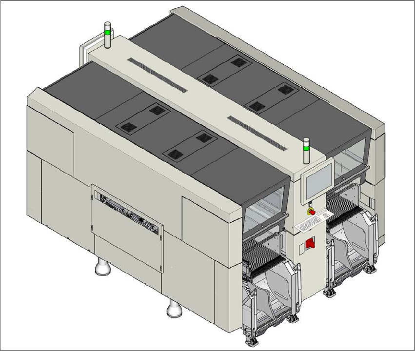
1.1.1 SIPLACE X4i S
1
Fig. 1.1 - 1 SIPLACE X4i S placement machine
The SIPLACE X4i S placement machine is distinguished by
– High precision,
– Intelligent placement optimization,
– Intelligent configuration strategies,
– Placement performance up to the high end process range

User manual SIPLACE X-Series 1 Introduction
From software version 708.1 Version 05/2015 1.1 Machine overview
19
Three placement methods are possible for processing the components:
– Collect&Place,
– Pick&Place and
– A combination of Collect&Place and Pick&Place (mixed mode).
The SIPLACE X4i S placement machine has four gantries. The two gantries in placement area 1
and the two gantries in placement area 2 point inwards.
These can be quickly and accurately positioned by linear motors, moving independently of one
another in the X and Y directions.
The SIPLACE X4i S placement machine has two placement areas, one single conveyor or one
dual conveyor. Two boards can be placed at the same time on dual conveyors.
There are four locations available for supplying components. These can be fitted with component
trolleys and configured with up to 40 tracks. At locations 2/3 or 1/4, the table positions for the rel-
evant placement area can be configured on the innermost or outermost position.
1.1.1.1 Overview of placement head configuration
1
CPP_H = Multistar CPP in high assembly position
CPP_L = Multistar CPP in low assembly position
Placement area 1 Placement area 2
C&P20 / C&P20 C&P20 / C&P20
C&P20 / C&P20 CPP_L/CPP_L
C&P20 / C&P20 TH / TH
C&P20 / C&P20 CPP_H/TH
CPP_L/CPP_L CPP_L/CPP_L
CPP_L/CPP_L CPP_H/TH
CPP_L/CPP_L TH / TH