SIPLACE X-Series (SIPLACE X-Series S, from SC 708.1) Edition 05/2015 EN User manual.pdf - 第201页
User manual SIPLACE X-Series 3 Technical data and assemblies From software version 708.1 Version 05/2015 3.9 X feeder modules for SIPLACE X-Series 201 3.9.7 T ray holder for the comp onent trolley of the SIPLACE X-Series…

3 Technical data and assemblies User manual SIPLACE X-Series
3.9 X feeder modules for SIPLACE X-Series From software version 708.1 Version 05/2015
200
3.9.6.1 Description
The energy and data interface allows X feeder modules to be used outside the machine and setup
area. The interface consists of an aluminum frame with omega profile (item 7 in fig. 3.9 - 18
, page
197
) for holding and guiding the feeder modules. As with the X component trolley, the feeder mod-
ule is placed on the omega profile, with the slider guides, and is pushed forwards until the front
centering pin of the feeder module is fully inserted into the locating hole (item 9 in fig. 3.9 - 18
,
page 197
). The locking latch (item 8 in fig. 3.9 - 18, page 197) locks the feeder module in this po-
sition. To remove the feeder module, simply press the release button (item 1 in fig.
3.9 - 18
, page 197 ). The locking latch (item 8 in fig. 3.9 - 18, page 197) is pressed down and re-
leases the feeder module. Fold-out feet (item 6 in fig. 3.9 - 18
, page 197) stabilize the position of
the energy and data interface, particularly for wide feeder modules.
The electronic housing (item 5 in fig. 3.9 - 18
, page 197) holds the electronic control unit for the
energy and data interface. The operator panel (item 2 in fig. 3.9 - 18
, page 197) consists of start
and stop buttons and two status LEDs. Communication with a PC takes place via the data cable
(item 3 in fig. 3.9 - 18
, page 197 ). The power supply cable (item 4 in fig. 3.9 - 18, page 197) is
connected to the power supply unit provided.
3.9.6.2 Usage
The energy and data interface is used to check, maintain and repair X feeder modules. It can also
be used for setting up in advance for PCB production. In this case, the energy and data interface
is fixed to the base plate (item 10 in fig. 3.9 - 20
, page 199). The tape reel holder (item 11 in fig.
3.9 - 20
, page 199) is also mounted on the base plate. When a component tape is inserted, you
can check or reset the increment, pick-up position and conveyor speed. The detailed user manual
describes how to use the interface and the necessary servicing work.
3.9.6.3 Scope of delivery
– Single Slot EDIF
– Power supply, 100 - 120 / 200 - 240 VAC, +30VDC, 4.3 A
– Base plate with tape reel arm
– User manual
User manual SIPLACE X-Series 3 Technical data and assemblies
From software version 708.1 Version 05/2015 3.9 X feeder modules for SIPLACE X-Series
201
3.9.7 Tray holder for the component trolley of the SIPLACE X-Series
Item no. 00141285-xxTray holder for X-Series
3
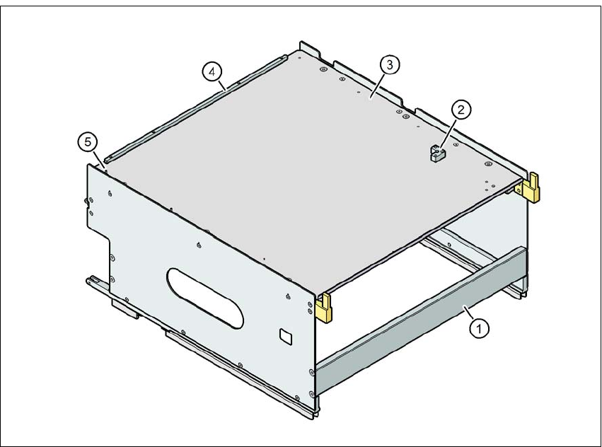
Fig. 3.9 - 21 Tray holder
(1) Tray holder for SIPLACE X-Series
(2) Bracket for 2nd JEDEC waffle pack tray
(3) Waffle pack tray carrier
(4) Stop bar for the JEDEC waffle pack tray
(5) Locating pin - zero point of JEDEC waffle pack tray
3
Individually placed JEDEC waffle pack trays or waffle pack magazines can be fixed to the waffle
pack tray carrier with magnets. If two JEDEC waffle pack trays are placed, these will need to be
fixed into place with locking bars or mounting rails, as used for the MTC waffle pack tray carriers.
Parts: Item no.:
Magnet 00316593-xx
Locking bar/mounting rail for JEDEC magazines 00372615-xx

3 Technical data and assemblies User manual SIPLACE X-Series
3.9 X feeder modules for SIPLACE X-Series From software version 708.1 Version 05/2015
202
3.9.7.1 Technical data
3
3.9.7.2 Number of waffle pack trays per location and machine
3.9.7.3 Inserting tray holder on the X-Series component trolley
Place the two front slider guides (item 1 in fig. 3.9 - 22, page 203) for the holder onto the in-
sertion aid (item 6 in fig. 3.9 - 22, page 203 ).
Push the holder along the guide profiles (item 7 in fig. 3.9 - 22, page 203), towards the front.
The holder slides with the front (item 1) and back slide guides (item 2 in fig. 3.9 - 22, page
203) on the guide profiles.
Continue pushing the holder, until the two centering pins "front" (item 4 in fig. 3.9 - 22, page
203) disappear into the centering holes (item 10 in fig. 3.9 - 22, page 203).
Check the two "back" centering pins (item 3 in fig. 3.9 - 22, page 203) for the holder. They
should slide easily into the recesses (item 8 in fig. 3.9 - 22, page 203) of the centering rail.
At the end stop of the holder, the locking latches (item 9 in fig. 3.9 - 22, page 203) engage
with the locking rollers (item 5) of the holder.
The waffle pack tray holder can be locked and released via the user interface. You can therefore
easily change the holder without interruption to machine operation.
Dimensions L x W x H 429 mm x 376 mm x 200 mm
Location occupied on the changeover table 32 locations
*a
*)a X feeder modules can be placed on the remaining 8 locations. When using locking bars/mounting rails, the
locations available are reduced to 6, due to the fixation lever which protrudes at the side.
Positioning options on X-Series placement ma-
chines
Locations 2 and/or 4
Placement head range TwinStar, CPP
*b
*)b Only permitted in high assembly position (CPP_H).
PLEASE NOTE
Further information
The maximum component height for the waffle pack tray holder depends on the maxi-
mum component height for the placement head used. When using waffle pack trays,
bear in mind that the components may not higher than the pickup height of a standard
feeder.
Placement machine Location 2 Location 4
X4 S 1 1
X3 S 2 1
X2 S 2 2