SIPLACE X-Series (SIPLACE X-Series S, from SC 708.1) Edition 05/2015 EN User manual.pdf - 第309页
User manual SIPLACE X-Series 5 Working with the machine From software version 708.1 Version 05/2015 5.10 Setting up the feeder modules 309 5.10.4.5 Splic e sensors for X t ape feeder modules S plice sens ors can be re tr…
5 Working with the machine User manual SIPLACE X-Series
5.10 Setting up the feeder modules From software version 708.1 Version 05/2015
308
5.10.4.4 Tape support for 8 mm X tape feeder module
5
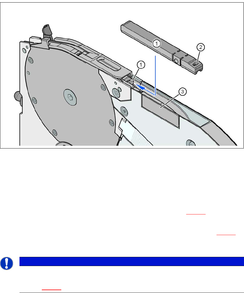
Fig. 5.10 - 8 8 mm X feeder module - tape support and splice sensor
(1) Tape support, removable
(2) Oval opening in the tape support
(3) Splice sensor installation location
The 8 mm X feeder module is equipped with a tape support (item 1 in fig. 5.10 - 8
). It can easily
be removed if necessary.
Insert the tang of a watchmaker's screwdriver into the oval opening (item 2 in fig. 5.10 - 8) in
the tape support and pull the tape support out against the direction of travel of the tape.
When you insert the tape support, make sure that it engages in its desired position.
5
5
PLEASE NOTE
Constant Z pickup height and reduction of time used to correct pickup heights
For all components size 0402 and smaller, always insert the tape support (item 1 in
fig. 5.10 - 8
) into the 8 mm X feeder module.

User manual SIPLACE X-Series 5 Working with the machine
From software version 708.1 Version 05/2015 5.10 Setting up the feeder modules
309
5.10.4.5 Splice sensors for X tape feeder modules
Splice sensors can be retrofitted to the X tape feeder modules. There are two versions of the sen-
sor:
Splice sensor for 8 mm and 12 mm X tape feeder modules
Splice sensor for 16 mm to 88 mm X tape feeder modules 5
The splice sensor is installed at the position indicated by item 3 in fig. 5.10 - 8
, page 308.
Tape feeder modules with a splice sensor already installed can also be supplied (see section
3.9.2
, from page 178).
5.10.5 Placing components on the 2x8 mm tape feeder module
The operation and configuration of 2x8 mm feeder modules is described in the "Tape Feeder Mod-
ule
2x8 mm X / Smart Feeder 12 mm X /16 mm X Job Guide".
Item number for German 00196664-xx
Item number for English 00196665-xx
5.10.6 Configuring components on the SIPLACE Smart Feeder
The operation and configuration of the SIPLACE Smart Feeder is described in the "Tape Feeder
Module
2x8 mm X / Smart Feeder 12 mm X /16 mm X Job Guide".
Item number for German 00196664-xx
Item number for English 00196665-xx
5 Working with the machine User manual SIPLACE X-Series
5.11 Observing displays on the X feeder module From software version 708.1 Version 05/2015
310
5.11 Observing displays on the X feeder module
5.11.1 Feeder module with LCD display
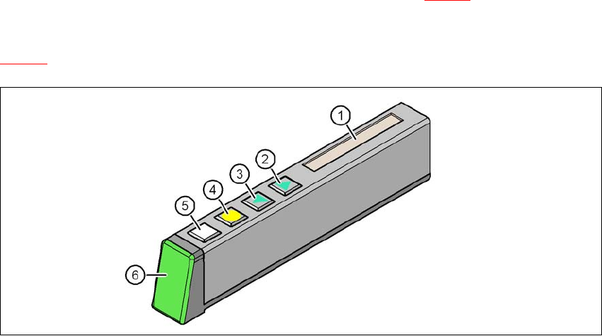
The X feeder modules have a multicolor status display (item 6 in fig. 5.11 - 1) for signaling the op-
erating
statuses and an LCD display (item 1 in fig.
5.11 - 1
).
5
Fig. 5.11 - 1 Buttons, LCD and status displays on the X feeder module
(1) LCD display
(2) FORWARD button
(3) BACK button
(4) FOIL button
(5) SET button
(6) Status display, multicolor