SIPLACE X-Series (SIPLACE X-Series S, from SC 708.1) Edition 05/2015 EN User manual.pdf - 第311页
User manual SIPLACE X-Series 5 Working with the machine From software version 708.1 Version 05/2015 5.11 Observing displays on the X feeder module 311 5.11.2 Feeder module with LED display The SIPLACE SmartFeeder have a …
5 Working with the machine User manual SIPLACE X-Series
5.11 Observing displays on the X feeder module From software version 708.1 Version 05/2015
310
5.11 Observing displays on the X feeder module
5.11.1 Feeder module with LCD display
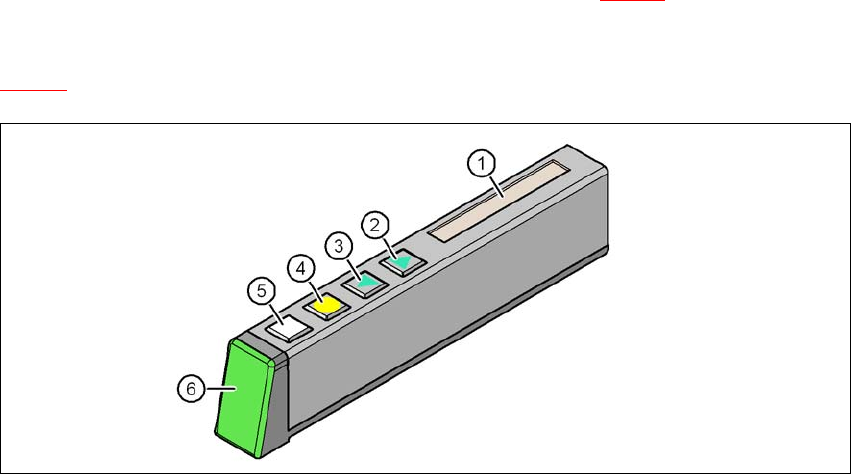
The X feeder modules have a multicolor status display (item 6 in fig. 5.11 - 1) for signaling the op-
erating
statuses and an LCD display (item 1 in fig.
5.11 - 1
).
5
Fig. 5.11 - 1 Buttons, LCD and status displays on the X feeder module
(1) LCD display
(2) FORWARD button
(3) BACK button
(4) FOIL button
(5) SET button
(6) Status display, multicolor
User manual SIPLACE X-Series 5 Working with the machine
From software version 708.1 Version 05/2015 5.11 Observing displays on the X feeder module
311
5.11.2 Feeder module with LED display
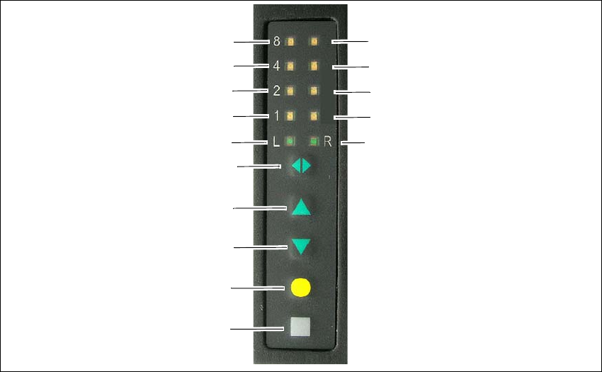
The SIPLACE SmartFeeder have a multicolored status display for each track and LED displays,
to indicate the operating states.
5
Fig. 5.11 - 2 Buttons, LED and status displays: Example of SIPLACE SmartFeeder 2x8 mm
(1) SET button
(2) FOIL button
(3) BACK button
(4) FORWARD button
(5) Track change button for switching between right and left
(6) LED L left track active
(7) LED 1 mm increment for left track
(8) LED 2 mm increment for left track
(9) LED 4 mm increment for left track
(10) LED 8 mm increment for left track
(11) LED R right track active
(12) LED 1 mm increment for right track
(13) LED 2 mm increment for right track
(14) LED 4 mm increment for right track
(15) LED 8 mm increment for right track
(1)
(2)
(3)
(4)
(5)
(6)
(7)
(8)
(9)
(10)
(15)
(14)
(13)
(12)
(11)

5 Working with the machine User manual SIPLACE X-Series
5.11 Observing displays on the X feeder module From software version 708.1 Version 05/2015
312
5.11.3 Status display
–Green:
The feeder module is on standby and is contained in the current setup.
– Orange:
A warning is being signalized. The text of the warning appears on the LCD display.
– Red:
A malfunction has occurred. The error message is output on the LCD display.
–Off:
The feeder module is not in the current setup.
5
5
5.11.4 LCD display
The following tables containing the wording of the LCD display, the color and the mode of the sta-
tus display, its meaning and troubleshooting measures.
5.11.4.1 Warnings and solutions
5
5
PLEASE NOTE
"LED off" only for feeder modules contained in the setup
The machine controller switches off the status display of any feeder modules not included
in the setup.
The "LED off" status only occurs when the programming system has preset a job on the
line. This takes some of the work away from the operator since he only has to watch
those feeder modules that are contained in the setup.
PLEASE NOTE
Setup procedure: Activation of LED for each feeder module
For the actual setup process - no setup information at the station, no job sent from SI-
PLACE Pro to the station/line - the LED on each feeder module is activated after the set-
up has been made. The operator is thus informed whether everything is OK.
Text on the
LCD display
Status
display
Meaning Solution
Remove Foil
(Remove the foil)
Orange The selected function is not
permitted when the cover foil
is tensioned (foil rocker is
pressed down).
If you wish to carry out that function, remove
the foil from the pair of gear wheels and cut
it off to relieve the pressure on the foil rocker.