SIPLACE X-Series (SIPLACE X-Series S, from SC 708.1) Edition 05/2015 EN User manual.pdf - 第386页
6 Station extensions User manual SIPLACE X-Series 6.8 Docking station for the component trolley of the SIPLACE X-Series From software ver sion 708.1 Version 05/2015 386 6.8.4 Controls and displays 6 Fig. 6.8 - 4 Docking …
User manual SIPLACE X-Series 6 Station extensions
From software version 708.1 Version 05/2015 6.8 Docking station for the component trolley of the SIPLACE X-Series
385
6
6
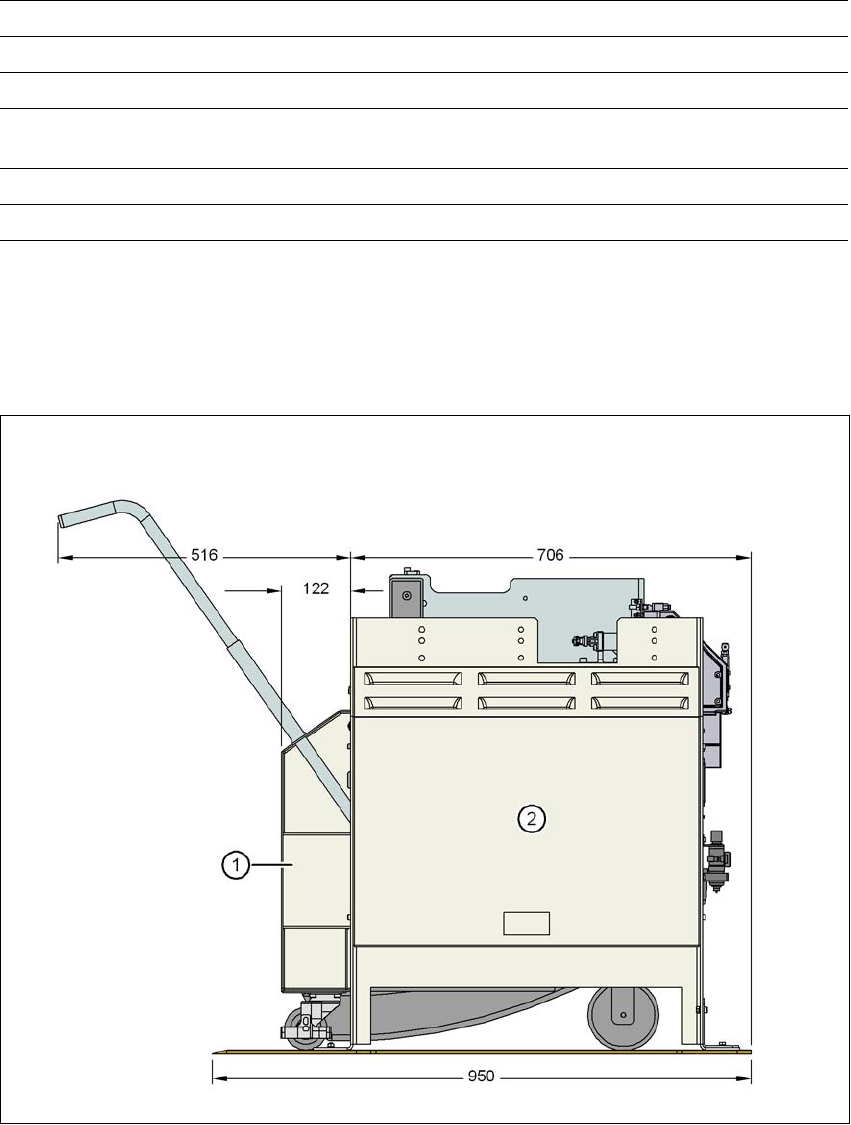
6.8.3 Dimensions of docking station with docked component trolley
6
Fig. 6.8 - 3 Docking station with docked component trolley - dimensions in millimeters
(1) Component trolley
(2) Docking station
Compressed air connection Connection plug KS 2-M5-A
Compressed air consumption 50 Nl/min
*a
Supply voltage 88 - 264 V~
Rated current 3.5 A (230 V~)
7 A (115 V~)
Nominal apparent power 0.8 kW
Fuse 2 x 8 A
*)a Under normal atmospheric conditions at 20°C and 1013 hPa
6 Station extensions User manual SIPLACE X-Series
6.8 Docking station for the component trolley of the SIPLACE X-Series From software version 708.1 Version 05/2015
386
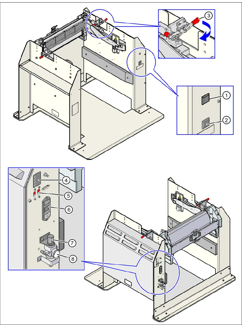
6.8.4 Controls and displays
6
Fig. 6.8 - 4 Docking station - controls and displays

User manual SIPLACE X-Series 6 Station extensions
From software version 708.1 Version 05/2015 6.8 Docking station for the component trolley of the SIPLACE X-Series
387
Legend for fig. 6.8 - 4
, page 386.
(1) Button with control lamp for mains power supply
(2) Button for locking and unlocking all feeder modules on the component trolley
(3) Clamping lever for fastening the changeover table - lever in position "closed"
(4) Label with diagram of switch S1 and S2 for addressing the CAN bus
(5) Switch S1 and S2 for setting the CAN bus address
(6) Mains switch
(7) Rotary knob for setting the operating pressure
(8) Manometer for showing the operating pressure