SIPLACE X-Series (SIPLACE X-Series S, from SC 708.1) Edition 05/2015 EN User manual.pdf - 第390页
6 Station extensions User manual SIPLACE X-Series 6.8 Docking station for the component trolley of the SIPLACE X-Series From software ver sion 708.1 Version 05/2015 390 6 Unscrew the two screwed connections (item 3 in …
User manual SIPLACE X-Series 6 Station extensions
From software version 708.1 Version 05/2015 6.8 Docking station for the component trolley of the SIPLACE X-Series
389
6.8.5.1 Tools
You will need the following tools to adjust the height of the COT insert:
– Allen wrench, set
– Fork wrench, SW 13
6.8.5.2 Converting the COT insert to other heights
6
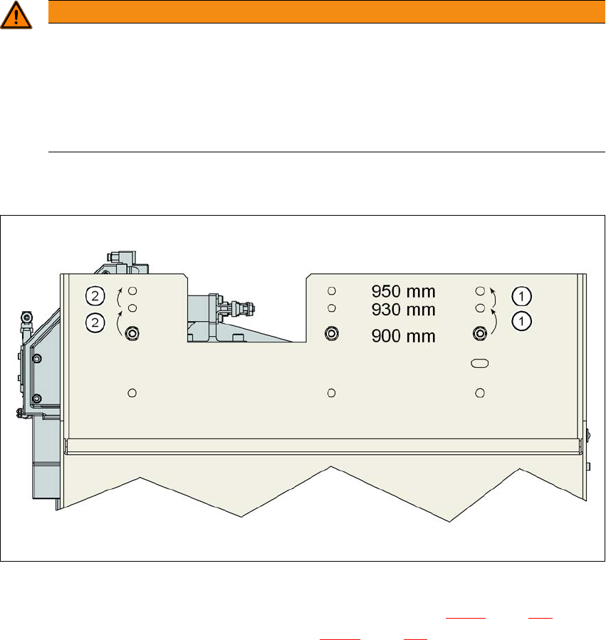
6.8.5.3 Converting the COT insert to heights of 900, 930 or 950 mm
6
Fig. 6.8 - 6 Order of conversion steps
Loosen the two hexagon socket-head screws M8x18 (item 9 in fig. 6.8 - 5, page 388) and re-
move the left and right guidance (item 8 in fig. 6.8 - 5
, page 388).
WARNING
Disconnect the docking station from the power supply.
Disconnect the docking station from the compressed air supply.
The weight of the COT insert is approx. 40 kg.
If required, enlist the help of a second person to help you with the conversion.
Follow the steps in the order described.
6 Station extensions User manual SIPLACE X-Series
6.8 Docking station for the component trolley of the SIPLACE X-Series From software version 708.1 Version 05/2015
390
6
Unscrew the two screwed connections (item 3 in fig. 6.8 - 5, page 388).
Loosen the two other screwed connections (item 2 in fig. 6.8 - 5, page 388).
Remove the two M8 hexagonal nuts and washers (item 4 in fig. 6.8 - 5, page 388).
Hold the COT insert by its side (item 10 in fig. 6.8 - 5, page 388) and remove the two hexagon
socket-head screws M8x40 here.
Swivel the COT insert to the next highest position.
Fasten the side panel at this point. Tighten the nuts loosely to do this.
Hold the COT insert by the FCU (item 12 in fig. 6.8 - 5, page 388) and remove the screwed
connections at item 2 in fig. 6.8 - 5
, page 388.
Swivel the COT insert to the next highest position.
Fasten the side panel at this point.
Check that all screwed connections at items 2, 3 and 4 are tightened firmly.
Fasten the right and left guidances (item 8 in fig. 6.8 - 5, page 388) with the hexagon socket-
head screw M8x18 (item 9 in fig. 6.8 - 5
, page 388).
6
CAUTION
Risk of damage!
When raising and lowering the COT insert, cables can be damaged.
When raising and lowering the COT insert, make sure that no cables are damaged.
PLEASE NOTE
If you want to lower the COT insert to a different height, follow the above instructions
in reverse order.

User manual SIPLACE X-Series 6 Station extensions
From software version 708.1 Version 05/2015 6.9 SIPLACE High-Force Head
391
6.9 SIPLACE High-Force Head
Item no. 00119736-xx High-Force Head
This item number only applies when ordering a new placement machine with a high force
head instead of a standard TwinStar. 6
6.9.1 Description
The SIPLACE high force head is an advanced development of the standard TwinStar. It can pro-
cess the same component range and also offers the possibility of achieving set-down forces up to
30 N. The SIPLACE high force head can use all the same nozzles and grippers as the standard
TwinStar.
6.9.2 Technical data
6
Al other technical data are identical for the TwinStar and high force head (see section 3.5.7.2,
page 150
).
Programmable set-down force 2.0 N to 10 N ± 10 %
greater than 10 N up to 30 N ± 15 %