M1series_ServiceManual_e.pdf - 第12页
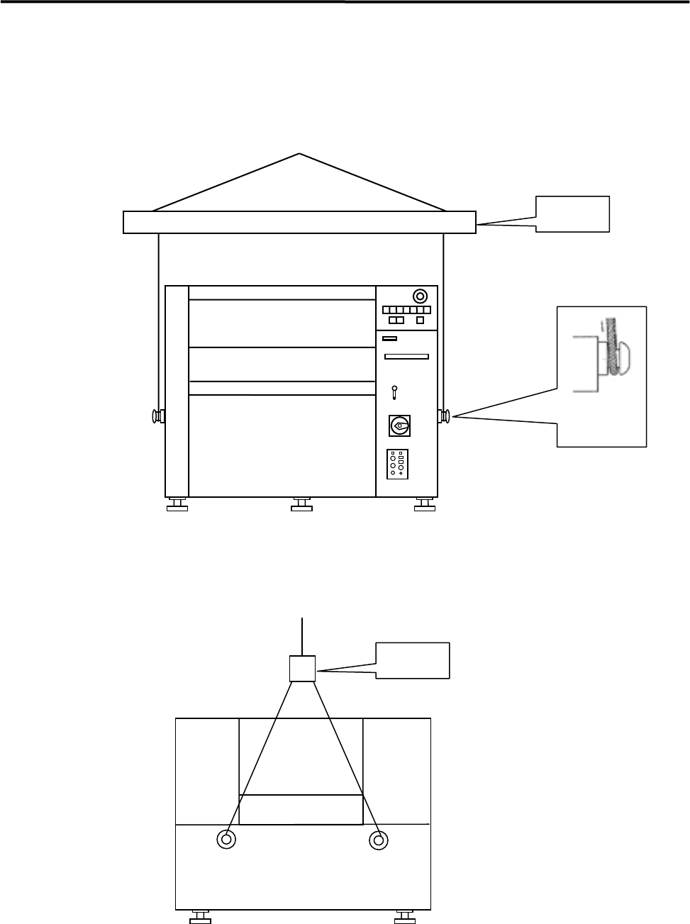
1 Installation 1-4 ■ How to Hoist Use the bolts, wires, and the arm as the foll owing diagram shows. Bolt Arm Front View Arm Side View NOTE: Be sure to use the arm to preven t the wire from touching the machine.
1 Installation
1-3
How to Hoist the Machine
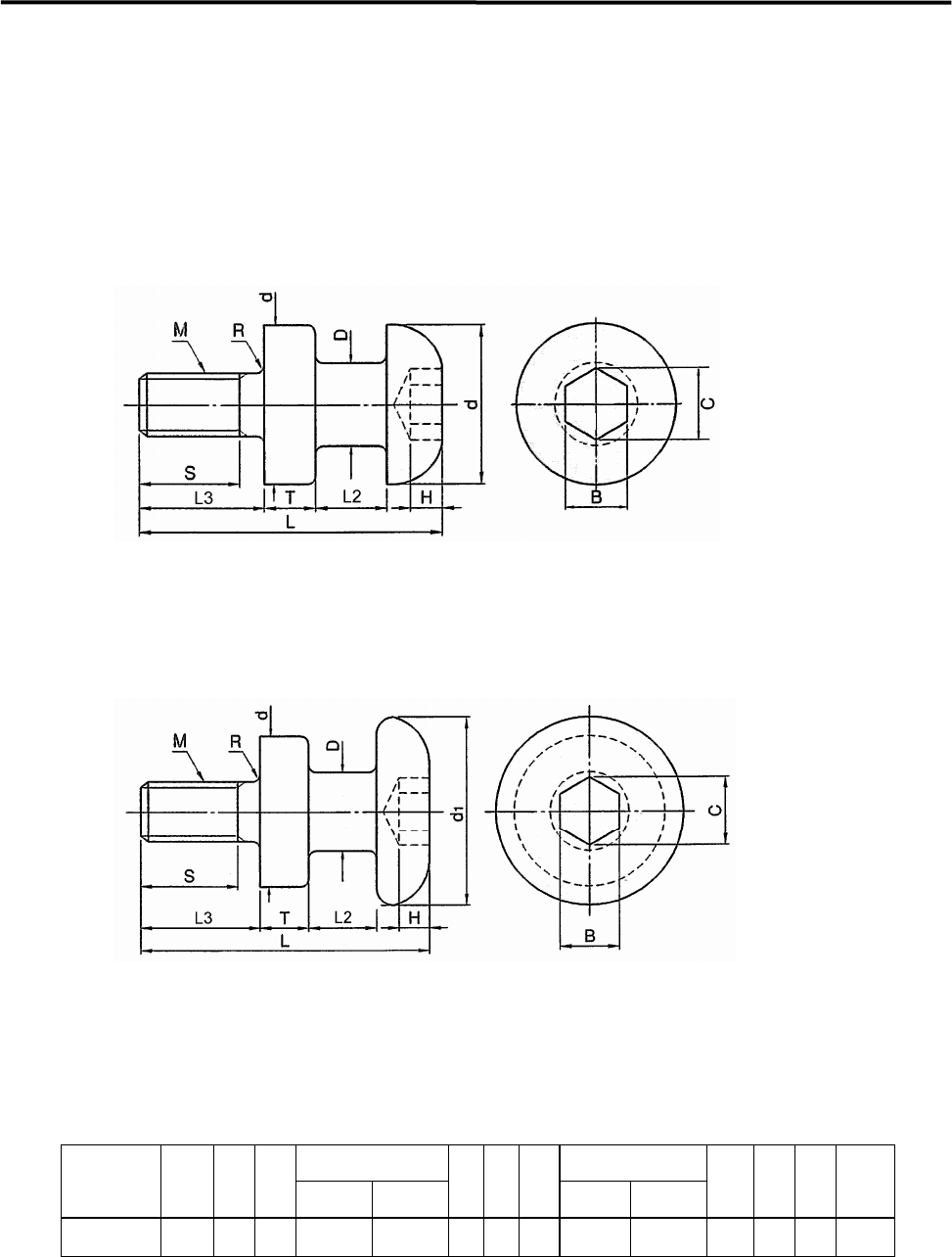
Be sure to use the bolts when hoisting the machine.
■ Recommended Bolt Size
● Type 1 (M20 x P2.5)
● Type 2 (M20 x P2.5)
[Unit = mm]
M x P D d d1 L2 L3 S T L R H B C
Type1 Type2
Type1 Type2
20x 2.5
25 48 62 20 28 37 32 16 90 98 2 12 17 19.8
1 Installation
1-4
■ How to Hoist
Use the bolts, wires, and the arm as the following diagram shows.
Bolt
Arm
Front View
Arm
Side View
NOTE: Be sure to use the arm to prevent the wire from touching the machine.
1 Installation
1-5
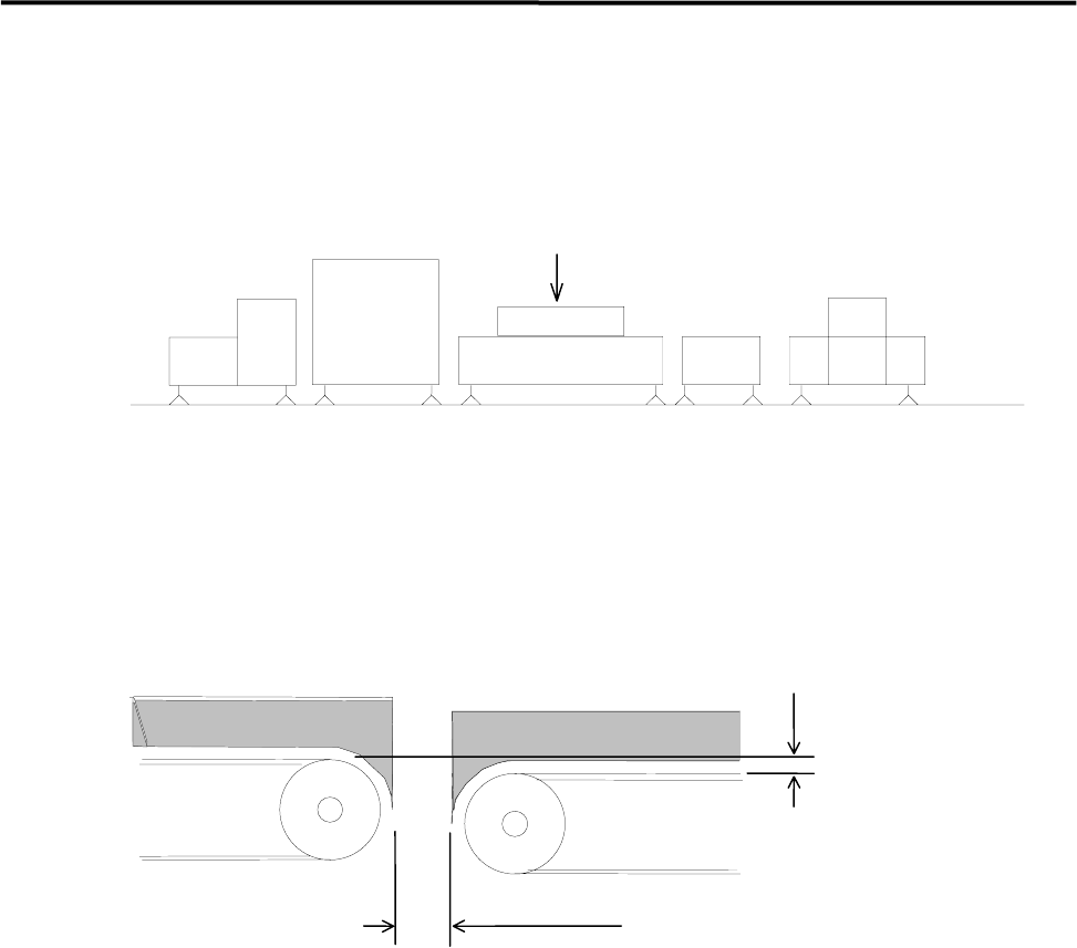
Production Line
To align your assembly line, first install the heaviest unit. Then install peripheral units using the first unit as
a reference.
Reference
Loader Mounter Reflow Oven Conveyor Unloader
To transfer the PCB (printed circuit board) smoothly, clearance between units are quite important. Be sure
that the clearance between units is approximately 5 mm as below figure shows. Adjust the height of the
downstream unit a little lower (0-0.5 mm) so that the PCB is transferred smoothly.
0 - 0.5mm
Approx. 5mm
DownstreamUpstream
側