M1series_ServiceManual_e.pdf - 第13页
1 Installation 1-5 Production Line To align your assembly line, first in stall the heaviest unit. Th en install peripheral u nits using th e first unit as a reference. Reference Loader Mount er Reflow Oven Conv eyor Unlo…
1 Installation
1-4
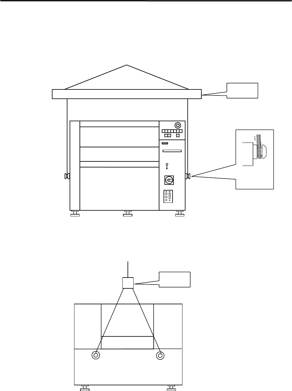
■ How to Hoist
Use the bolts, wires, and the arm as the following diagram shows.
Bolt
Arm
Front View
Arm
Side View
NOTE: Be sure to use the arm to prevent the wire from touching the machine.
1 Installation
1-5
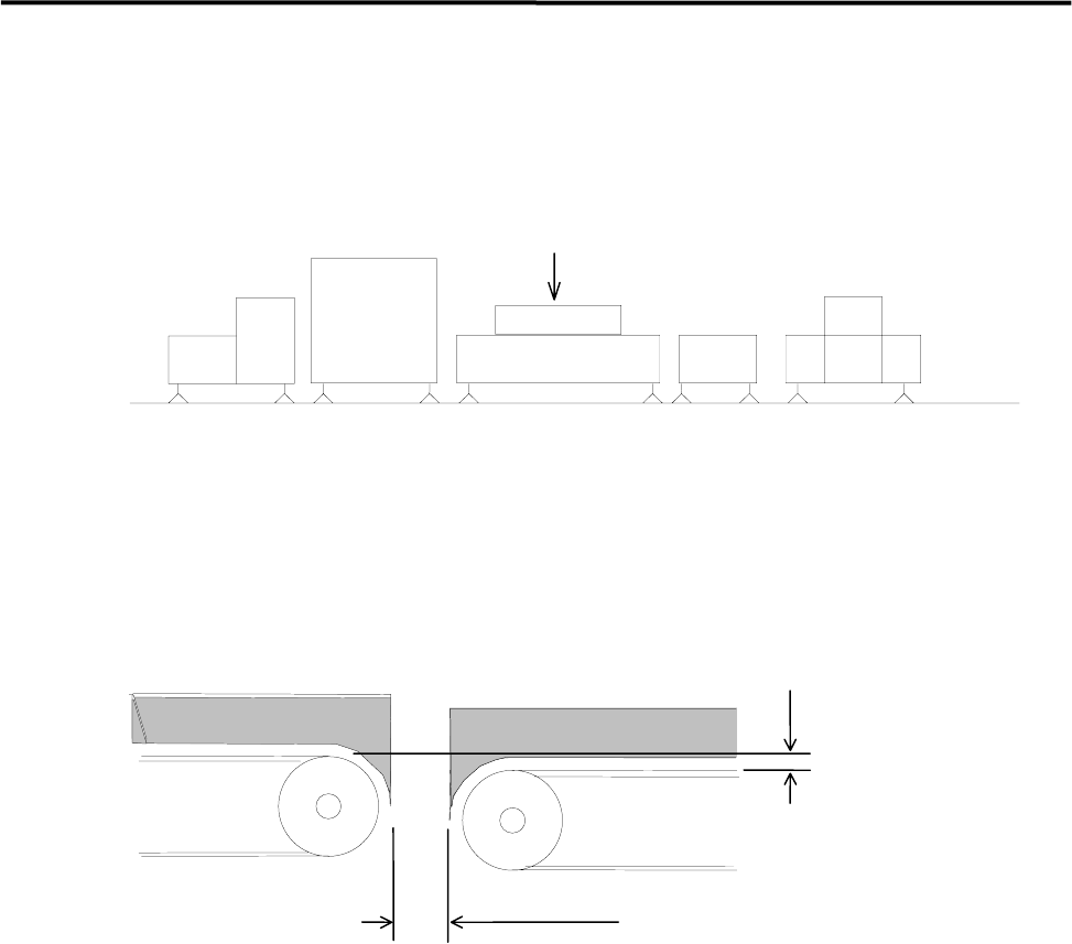
Production Line
To align your assembly line, first install the heaviest unit. Then install peripheral units using the first unit as
a reference.
Reference
Loader Mounter Reflow Oven Conveyor Unloader
To transfer the PCB (printed circuit board) smoothly, clearance between units are quite important. Be sure
that the clearance between units is approximately 5 mm as below figure shows. Adjust the height of the
downstream unit a little lower (0-0.5 mm) so that the PCB is transferred smoothly.
0 - 0.5mm
Approx. 5mm
DownstreamUpstream
側
1 Installation
1-6
Installing the Machine
Do not touch terminals of electric components when the power is on to prevent electric shock and machine
damage.
Warning
Make sure to ground the machine to prevent electric shock.
Warning
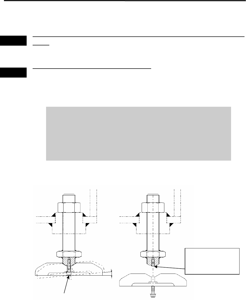
Note on Installation
It is normal that the adjust foot can be slightly inclined (within 2-degree range).
Do not tighten the bolt forcedly trying to fix the foot.
When you move and/or install the mounter, be careful not to apply excessive
force on the adjust foot. This may cause the screw of the adjust foot to break.
When placing the mounter on the floor, be sure that the mounter is kept
horizontal.
2°
Mounting Screw
If excessive force is
applied, the screw may
break at this point.