M1series_ServiceManual_e.pdf - 第34页
3 Mechanical Section 3-6 Nozzle holder A ball and spring that hold t he nozzle may not perform smoothly due to t he entry of dust and dirt, which will cause a nozzle-dropping. Make a periodic check of the nozzle escape. …
3 Mechanical Section
3-5
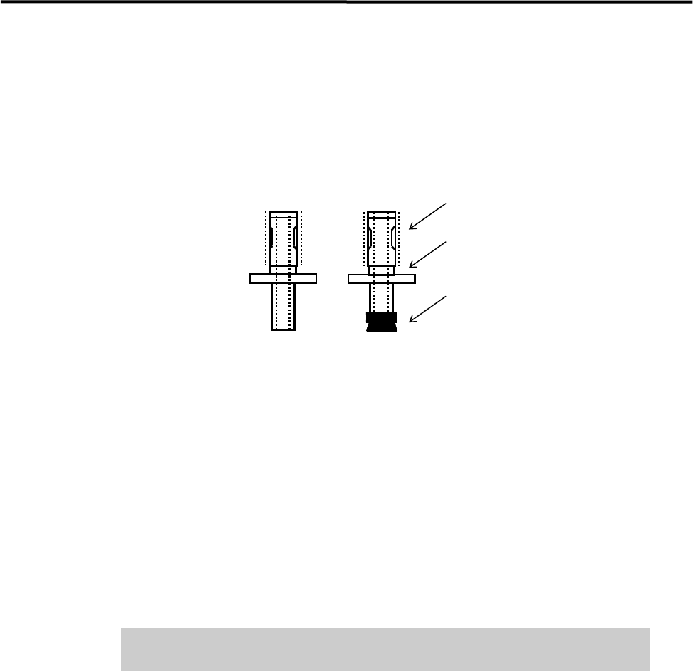
■ Checking of Suction Pad (for nozzle No. M017, M018, M019, M020)
Check the rubber suction pad at the tip of the nozzle for flaws and cracks. If you find a flaw or crack,
replace the pad with a new one.
First, pull off the old pad, and then apply some grease to the inner surface of the new pad to fit it to the
nozzle.
Apply silicone grease.
Identification Mark
Suction Pad
■ Applying Silicone Grease
After cleaning a nozzle, be sure to apply grease to the nozzle.
● Outer Surface
Apply small amount of silicone grease to the outer surface (indicated by thick dotted line). And then wipe
off the grease with a dry cloth to make a very thin film of grease.
● Suction Pad
Use grease to prevent the rubber suction pad from degrading. Apply small amount of silicone grease to the
outer surface of the pad. And then wipe off the grease with a dry cloth.
Do not apply excessive grease, which may cause the nozzle to clog with dirt
and result in the placement error.
3 Mechanical Section
3-6
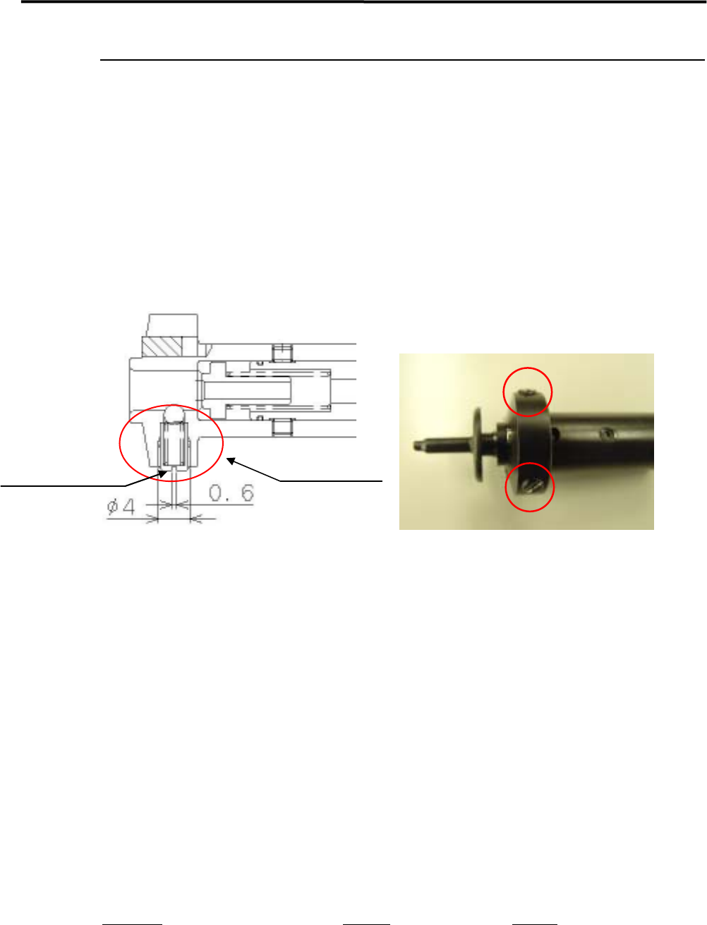
Nozzle holder
A ball and spring that hold the nozzle may not perform smoothly due to the entry of dust and dirt, which
will cause a nozzle-dropping. Make a periodic check of the nozzle escape. If any *abnormal conditions are
seen, clean the nozzle holder. (*The nozzle stays up and does not go back to its initial position, or the nozzle
drops easily etc.)
NOTE: Please handle the spring and ball inside the nozzle holder carefully, since they tend to get lost. It is
recommended that spare parts should be kept handy and start removal.
Spring holder
Nozzle holding parts
ACTION:
① Remove the spring holder with a flat blade screw.
NOTE: Adhesive has been applied around the screw head to prevent loosening. When removing the spring holder
for the first time, take off the adhesive and start removal.
② Take the spring and ball out.
(When it is difficult to take the ball out, push it from inside of the nozzle holder.)
③ Remove the spring from the spring holder with tweezers.
④ Remove dust and dirt around the hole area, the spring and ball.
⑤ Apply the proper amount of Silicone Grease to the spring and ball.
Put them back in reverse order of removal. Fasten the spring holder until it touches the inner wall.
Part Name
Part No. Remark
HOLDER,SPRING LG0-M714P-00X Spring holder
SPRING,COMP. LG0-M71CC-00X Spring
STEEL,BALL LG0-M71B5-00X Ball
3 Mechanical Section
3-7
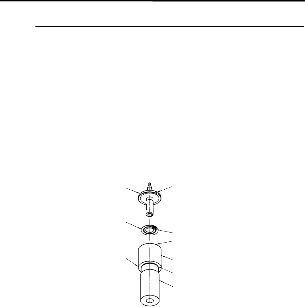
Nozzle Recognition Stickers
Labeling a Nozzle ID Sticker to a Nozzle
ACTION:
① Wipe off oil, dust, or water from the upper side of the nozzle flange with alcohol.
② Slide the ring of the labeler until the groove in the labeler shaft appears.
③ Peel off the sticker from its slip sheet using tweezers.
④ With the sticker’s adhesive side upward, align the sticker’s angle mark to the ring’s positioning mark.
Set the sticker into the ring, being careful not to touch the sticker’s adhesive side.
⑤ Make sure the sticker is properly placed in the ring.
⑥ Insert the nozzle upside down into the hollow of the labeler shaft, while aligning the nozzle cutoff to
the ring’s positioning mark.
⑦ Push up the labeler shaft so that the sticker sticks to the nozzle flange.
Nozzle
Cutoff
Nozzle ID sticker
Positioning mark
Ring
Groove
Shaft
Labeler for
nozzle ID sticker
Angle mark